|
January 1973 Popular Electronics
 Table of Contents Table of Contents
Wax nostalgic about and learn from the history of early electronics. See articles
from
Popular Electronics,
published October 1954 - April 1985. All copyrights are hereby acknowledged.
|
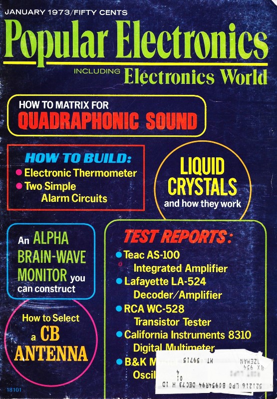
This article on noise
measurement is not about electrical noise, but rather on audible noise. It appeared
in a 1973 edition of Popular Electronics magazine during an era when hi-fi
stereo equipment was becoming a big deal. Author Carl Alsen, an engineer at
General Radio,
reviews methods of sound level measurement and gives values for some usual and unusual
sources typically found in manufacturing environments, like a punch press, pneumatics
rock drill, office and restaurant environments, and the rustling of leaves. Radio
manufacturers had/have a vested interest in background noise that affects the satisfaction
of their customers. Ambient noise in all realms has been a rapidly growing problem
in terms of information transmission and reception. Many articles were written about
background interferences in the decades of the 1960s and 1970s as more and more
people became engaged (e.g.,
Electronic Pollution ... An Impending Crisis,
Acoustical Tile - A New Hi-Fi Component,
The Dolby Technique for Reducing Noise, etc.).
Important Factors in the War on Noise Pollution
 By Carl W. Alsen, General Radio, Concord,
Mass. By Carl W. Alsen, General Radio, Concord,
Mass.
Studies in acoustics-particularly psychoacoustics - require measurements of the
effect of sound upon people themselves and their hearing. Since our hearing is decidedly
nonlinear in response, so also must be the measuring instruments.
Over the years, a number of specialized sound measuring instruments have been
developed for the acoustics specialist. Today, however, noise has become a common
worry of a host of nonspecialists. The airport manager, plant engineer, and manufacturer
of noise-generating snowmobiles, power mowers, and all manner of appliances must
concern themselves with the noise problem and people's reactions to the noise itself.
To satisfy the consumer and the growing number of noise-control laws being passed,
these nonspecialists must make noise measurements. Hence, what was once the specialist's
instrument is rapidly becoming the nonspecialist's weapon in the battle against
noise.
To understand how noise-measuring instruments operate requires some knowledge
of the ear mechanism and how it behaves.
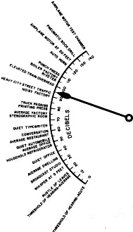
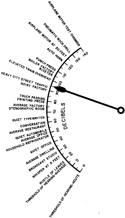
Fig. 1 - Normal sounds fall in range from 0 to 140 dB. Instruments
which are used to measure sound read in dB.
The Intriguing Ear. One startling fact about the human ear is
that it can handle an immense variation in sound intensity. A high-level sound just
short of the pain-threshold is 10,000,000 times as intense as the quietest sound
the ear can detect. The whole hearing mechanism responds to this wide range of sounds
in an exponential manner such that noise increased three-fold appears to the human
ear as though it only about doubled. Hence, by expressing sound level in logarithmic
form, we have an approximate expression of loudness. For this reason, and because
smaller numbers are easier to handle, the decibel, abbreviated "db" in scientific
notation, has been adopted as the unit of measure for sound level.
The decibel is defined as 20 times the logarithm of the ratio of sound pressure
level to a reference level, or 0 dB. As shown in Fig. 1, normal sounds covering
a ratio of levels of 10,000,000: 1 can be expressed over a 140-dB range. About the
smallest normally perceptible change in sound intensity is 1 dB. All sound-measuring
instruments give readings in terms of decibels.
As concerns frequency response, human hearing is not as flat as even the poorest
"high-fidelity" audio system, varying as much as 50 dB (a ratio of 300:1) from 50
Hz to 10,000 Hz. Even more perverse is the fact that this response changes with
sound level; the response to high-level sounds is the best, but still not very good.
A common evidence of this effect is the necessity of boosting the bass response
of an audio system at low levels to keep the effect of flat, or at least pleasing,
response.
Like any mechanical system, the human ear has an elastic limit beyond which temporary
or even permanent damage can occur. Depending on many factors - the nature of the
noise and the individual himself - this can occur at levels as low as 85 dB. Recent
federal legislation has imposed limits upon the noise levels to which employees
may be exposed in industrial plants. In a characteristically nonlinear fashion,
permissible levels depend upon the duration of the exposure to the noise.
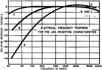
Fig. 2 - The curves show weighted response characteristics
specified by the American National Standards Instruments.
Finally, we find nonlinear effects the most unpredictable because the listener
is a human being. The irritation a noise generates depends upon the emotional state
of the listener at any given moment as much as it does upon the level or frequency
of the sound itself. We are further confounded by the many other little-understood
psychological facets of hearing, like our ability to sort out one voice in a general
din.
Earlike Instruments. If measuring tools are going to be useful
to the acoustician or psychoacoustician, they must simulate one or more of the peculiar
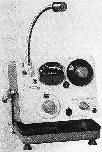
nonlinearities of human hearing. The basic sound-measuring instrument is the sound
level meter (SLM). The term "sound level meter" describes a very particular set
of characteristics defined by the American National Standards Institute in Standard
S1.4-1971. In simple terms, the sound level meter is an a-c voltmeter with a microphone
to convert sound energy into an a-c voltage. The addition of a step attenuator,
some special filtering networks, and a shaped-characteristic meter sets it apart
as a sound level meter.
To simulate the logarithmic response of the human ear, the sound level meter
is equipped with a meter movement designed to compress the reading so that the scale
spans about 16 dB (a ratio of 40:1) and is approximately linear throughout its scale.
The attenuator is adjustable in about ten steps of 10 dB each so that, with the
range of the meter, a total measuring range of about 30 to 150 dB is attained. As
a logarithmic voltmeter, the SLM has a range of about 5 μV to 5 V rms. Many models
can be adapted for use as audio rms voltmeters by the substitution of a connector
for the microphone.

Octave-band noise analyzer permits a rapid frequency analysis
of noise to aid identification and treatment of separate sources of noise components.
The ear's frequency response, depressing to an audiophile, is also a problem
to the SLM designer. The ANSI standards for the SLM specify A, B, and C weighting
curves (Fig. 2). These were originally designed to approximate human hearing
frequency response at levels below 55 dB (A weighting), from 55 to 85 dB (B weighting),
and above 85 dB (C weighting). Now, however, the A-weighted sound level is the most
widely used regardless of the intensity of the sound to be measured. In fact, the
industrial noise provisions of the Occupational Safety and Health Act of 1970 specify
A-weighted, dB (A), measurements.
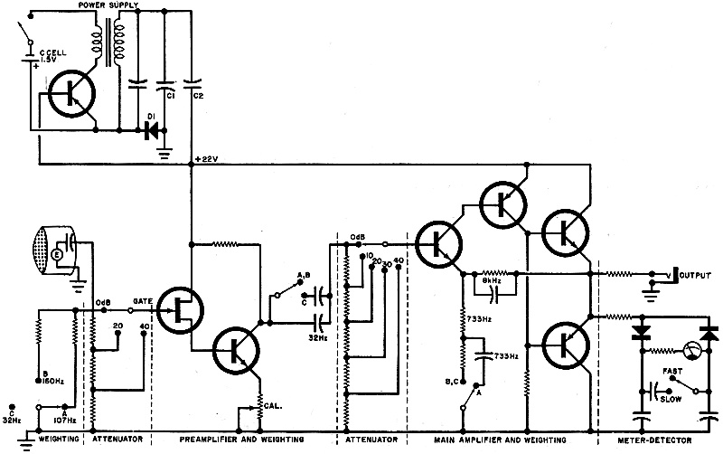
SLM Circuits. To achieve the required weighted responses in
one sound level meter (Fig. 3), weighting networks are inserted into each coupling
and feedback path. The feedback network in the main amplifier provides the 6 dB/octave
roll-off at 8000 Hz required for each weighting curve. The C weighting, the most
nearly flat of the weighted responses, has a specified low-frequency roll-off at
32 Hz, which is inserted in the coupling between the preamplifier and main amplifier.
This is switched out for the B and A weighting. Low-frequency roll-off for B weighting
is accomplished at the input to the preamplifier with a shunt resistance across
the microphone capacitance for roll-off at 160 Hz. Response shaping at this point
in the circuit helps reduce the likelihood of overloading the amplifier. A weighting,
the most sharply modified response, is obtained with the addition of a 733-Hz
roll-off network in the main amplifier and continued use of the microphone capacitance
for an even faster roll-off below 107 Hz.
Attenuation is introduced in two sections for best signal-to-noise performance
and overload control. As attenuation is required, it is first added between the
preamplifier and main amplifier, reducing preamplifier noise as well as the signal.
Beyond 40 dB, attenuation is added at the input to the preamplifier to reduce the
signal from high-intensity sound, preventing overloading. Through the distribution
of both weighting and attenuation networks, each stage of the amplifier is able
to operate on signals of optimum size.
 The simple dc-to-dc converter circuit,
which permits operation from a single 1.5-volt C cell, is basically a tuned self-biased
Class-C oscillator operating at 130,000 Hz. The transformer output is applied to
a full-wave voltage doubler rectifier consisting of diode D1, the transistor's base-emitter
junction, and capacitors C1 and C2. Half of the dc output voltage biases the transistor
in the cutoff region. This class C operation results in about 70 percent conversion
efficiency and 50 hours of instrument operation from one C cell. The simple dc-to-dc converter circuit,
which permits operation from a single 1.5-volt C cell, is basically a tuned self-biased
Class-C oscillator operating at 130,000 Hz. The transformer output is applied to
a full-wave voltage doubler rectifier consisting of diode D1, the transistor's base-emitter
junction, and capacitors C1 and C2. Half of the dc output voltage biases the transistor
in the cutoff region. This class C operation results in about 70 percent conversion
efficiency and 50 hours of instrument operation from one C cell.
Measuring Noise Danger. Today's growing concern with noise pollution
in industry centers on hearing damage and on annoyance that results in increased
irritability and lowered productivity. The length of exposure to loud sounds must
be considered in the evaluation of potential danger. The current laws state that
any exposure to levels above 115 dB (A) is too much, while unlimited exposure is
permissible to sound levels of less than 90 dB (A). Intermediate levels are permissible
for limited periods of . time, as shown in the Permissible Noise Exposure Table.
A sound level meter can be used to monitor noisy areas, but to determine the
legality of the noise by these standards requires frequent measurements over a working
day, followed by calculations to combine the contributions of the various levels
measured and their durations.

Fig. 3 - Weighting networks are used in the sound level
meter to achieve the responses as shown in Fig. 2. Each weighting gives a different
roll-off.
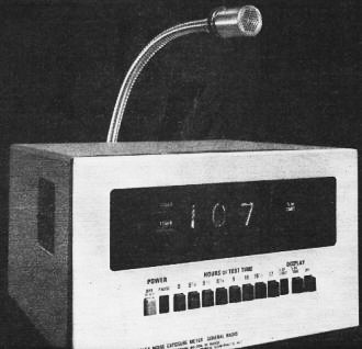
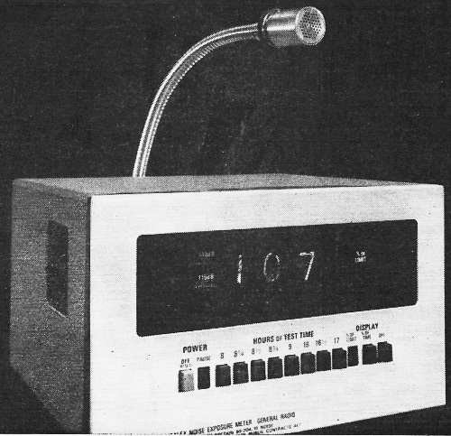
A noise exposure meter combines a sound level meter and an exposure
calculator designed to provide unattended operation and a correct readout.
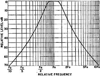
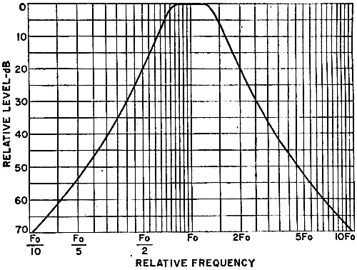
Fig. 4 - In an octave-band filter, the 3-dB points are just
an octave apart.
To eliminate the tedium of such measurements and the chance of calculation errors,
a noise exposure monitor has been developed to operate unattended for a full working
day, measuring and calculating under control of an internal timer. Once turned on,
the monitor makes regular A-weighted measurements of the sound level, determines
which band the noise falls into, and accumulates counts at a rate in proportion
to the severity of the noise.
Monitors designed for in-plant installation display the accumulated counts as
a reading of the percent of allowable total exposure. Small monitors designed to
be worn when an employee moves from place to place hold this exposure information
to be read out at the end of day on a combination indicator/battery checker/calibrator.
Panel lamps on each indicate if the instantaneous level has at any time exceeded
115 dB for 0.5 second or longer, and if sounds in excess of 140 dB have been detected
no matter how short their duration.
Other Noise-Measuring Instruments. For further analysis of sounds
in a manner equivalent to human hearing, frequency analyzers are available with
constant-percentage-bandwidth filters. Since we hear octaves as equal intervals
of tone, it is desirable in the analysis of noise frequencies to use filters that
are an octave or fraction of an octave wide. These filters can be a single filter
that is continuously tunable, a series of filters that can be switched in steps,
or many filters in parallel. But the bandwidth is usually a fixed percentage of
the center frequency, about 70 percent wide for octave-band filters (Fig. 4)
and about 26 percent for 1/3-octave bands.
Impulse noises, like those produced by explosions or punch presses, can have
serious effects on hearing and, so, need to be measured. Meter movements are typically
too sluggish to respond to brief noise impulses and the eye too slow to note accurately
even the peak value. Storage oscilloscopes greatly aid in the analysis of short-duration
noises, but they do not provide simple numerical readings and are difficult to use
in the field.
An impact noise analyzer has been developed to capture the fleeting characteris-tics
of impulse noise with storage circuits. The "quasi-peak" integrator circuit with
a 0.25-ms rise time responds very quickly to the rising level of an impulse. A built-in
sluggish decay time (about 600 ms) permits the operator to "eyeball" an approximate
peak value more easily. While this is happening, a "peak" storage circuit with a
50-μs rise time holds a voltage, related to the peak sound level, to be read
at the operator's leisure. Another storage circuit is charged from an averaging
detector with a selectable time constant. A "time average" reading taken from this
storage circuit will be proportional to the duration of the impulse. From these
three quantities - quasi-peak, peak, and time-averaging - the impulse can be well
defined and compared with the characteristics of other known noises.
The electronics industry has provided the field of acoustics with an arsenal
of sophisticated measuring tools that do an excellent job of simulating the peculiar
behavior of human hearing. But much still remains to be done. In medicine, transportation
control, communications, and computers, the greatest challenge will be to ensure
that human needs and peculiarities determine the performance of electronic systems
- not the reverse.
Posted March 7, 2024
(updated from original post
on 10/23/2017)
|