|
March 1971 Popular Electronics
 Table of Contents Table of Contents
Wax nostalgic about and learn from the history of early electronics. See articles
from
Popular Electronics,
published October 1954 - April 1985. All copyrights are hereby acknowledged.
|
In the days before just
about every multimeter had a built-in diode and transistor tester, there was not
much - if anything - available for the hobbyist. Some of the vacuum tube test sets,
like my 1961 vintage
B&K Dyna-Quik
Model 650, surprisingly included diode and transistor test sockets. This
article for a "non-destructive" type - as opposed to the popular "destructive"
type - homebuilt transistor tester appeared in a 1971 issue of Popular Electronics
magazine. It can identify PNP vs. NPN, measure DC gain, and measure leakage current.
The tester will verify diode integrity as well. There's also a bonus "Parts Talk"
comic on the page at no extra cost.
Check or Match Transistors and Diodes
 By John L. Keith By John L. Keith
Buying surplus or bargain-package transistors is a little like buying a pig in
a poke. Especially if you get one of those so-called "computer boards" to which
several transistors, usually unmarked, are connected. You may get some real high-quality,
expensive units - some others may be completely useless. For the most part, the
transistors that are in operating condition can be put to good use by the experimenter,
provided he can sort them out as to type and identify their parameters, This can
be done of course with a good transistor checker but not everyone has one of those
so the simple transistor tester described here comes in very handy and saves time
and money.
The transistor tester can be used to check either NPN or PNP transistors and
will measure leakage down to 10 μA and collector current to 10 mA. You can measure
ICO, IC (with 20 or 100 μA of base current), ICEO,
ICES, and IEO (see sidebar for definitions). Diodes can also
be checked by connecting them between the collector and emitter pins of the test
socket. The tester is also useful for checking two transistors that must be matched
for a specific application.
The tester has been designed so that it will check almost any type of transistor
and cannot harm a unit regardless of the switch positions or the way the transistor
is connected to the test socket.
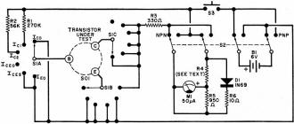
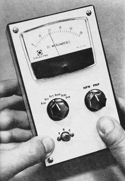
Fig. 1 - All major transistor parameters can be checked using
this tester since the novel circuit enables measurements from a low of 10 microamperes
to high of 10 milliamperes.

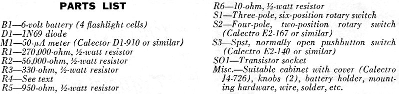
Parts List
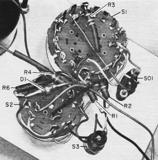
All the components except the battery are mounted on the front
panel. The small parts such as resistors. capacitors and diodes are soldered directly
to the two switches.
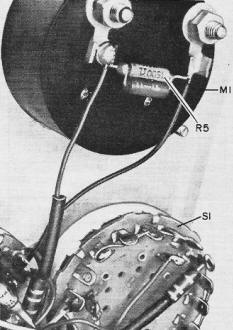
Two resistors in parallel are used to make up the meter shunt
resistor (R5) in order to obtain the required resistance value. Here again the components
are mounted directly on the meter terminals.
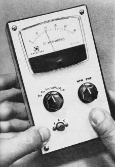
Construction. As shown in the photographs, the prototype was
built in a conventional plastic utility box with all components except the batteries
mounted on the cover and with point-to-point wiring. The circuit is shown in Fig. 1.
The internal resistance of the meter movement is an integral part of the circuit.
The combined resistance of the meter, R5, and R4 must be 12,000 ohms. The value
of R4 must be chosen to obtain this value as closely as possible. With the meter
specified in the Parts List, R4 should be about 11,000 ohms, This insures full compression
and, with the circuit of D1 and R6, provides a full-scale reading of 10mA.
Operation. Insert the transistor to be tested in the test socket,
place S1 on either IC1 or IC2, and depress pushbutton switch
S3. The meter should deflect upscale when S2 is in the proper position. The position
of the switch for upscale deflection determines whether the transistor is NPN or
PNP.
To check the DC gain (HFE) of the transistor, place S1 on either IC1
or IC2, depress S3, and note the meter indication. Then determine the
gain from the conversion table. Note that position IC1 is for a base
current of 20 μA while position IC2 supplies a base current of 100 μA.
The gain is different for the different base currents. The other four positions
of S1 are to test for leakage currents. Obviously, the less leakage in any case,
the better. In these tests, the meter indicates directly in microamperes.
To check a diode, connect it between the emitter and collector pins of the test
socket and place S1 in either the IC1 or IC2 position. Depress
S3 and note the meter readings when S2 is in the NPN and PNP positions. Ideally,
in one position, the meter should indicate full scale and it should give no indication
in the other position-indicating that the diode conducts in one direction and not
the other. The lower the ratio between the two readings, the poorer the diode.
Parameter Definitions
ICEO - Collector current with base open. The polarity of the applied
voltage is such that the collector-base junction is biased in a reverse direction.
ICES - Collector leakage current with base shorted to emitter. Equivalent
to the leakage current of collector diode if emitter junction were not present.
The polarity of the applied voltage is such that the collector-base junction is
biased in a reverse direction.
IEO - Sometimes called IEBO. Emitter-base current with
collector open. The polarity of the applied voltage is such that the emitter-base
junction is biased in the reverse direction.
ICO - Sometimes called ICBO. Collector-base current with
emitter open. The polarity of the applied voltage is such that the collector-base
junction is biased in the reverse direction.
IC - Collector current - depends on the amount of base current supplied.
A measure of DC gain (HFE).

Posted March 27, 2019
|