|
March 1958 Popular Electronics
 Table
of Contents Table
of Contents
Wax nostalgic about and learn from the history of early electronics. See articles
from
Popular Electronics,
published October 1954 - April 1985. All copyrights are hereby acknowledged.
|
Nixie tubes were used for
numeric - and sometimes alpha - displays back in the days before LEDs and LCDs.
They were more light bulbs than tubes, but were encapsulated in evacuated glass
shells like vacuum tubes and had round, multi-pin bases like tubes. Separate filaments
were provided for each character. There were two basic varieties: characters that
displayed through the top of the tube, and characters that displayed through the
side of the tube. "Play Games with Nixie Tubes" is the cover story for this
March 1958 issue of Popular Electronics magazine. Nixie tubes are popular with builders of retro equipment, and
a lot of products are available for sale that incorporate them; e.g., clocks,
wrist watches, radios,
clock radios, calendars, games, and much more. Electronic test
equipment and medical instruments were big users of Nixie tubes. I remember a couple
of the signal generators we used on the MPN-14 radar has Nixie tube displays. Supposedly
the name "Nixie" derived
from "NIX I", an abbreviation of "Numeric Indicator eXperimental No. 1," as designated
by the Burroughs Corporation sometime around 1955.
Nixie tubes for this project can be purchased on eBay.
Play Games with Nixie Tubes
 by Harvey Pollack by Harvey Pollack
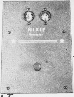
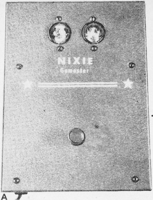
Nixie Gamester installed in its grey aluminum cabinet. Activating
button is in the center of the front panel.
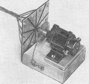
Completed motor and wiper assembly.
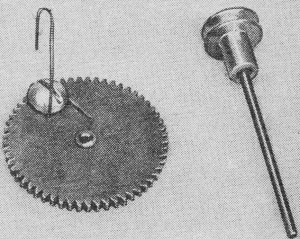
Large gear with wiper wire in place. Small pulley and shaft are
not used.
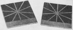
Commutators after etching. The copper is entirely removed between
segments. leaving ten 36° wedges of copper. Note bare 1/2" strip at bottom.
You can throw away the whirling number wheels, the tumbling golf balls in the squirrel
cage, and the gallopin' dominoes! It's, much more fun to play Bingo, Roulette, Put-and-Take,
Quizzo, boy-girl parlor games, and a host of other games - electronically! By merely
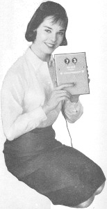
pressing a button, you can display a pair of randomly selected numbers for all kinds
of numerical games in shining neon lights visible up to 20 feet away.
This simple form of digital presentation is made possible by a modern little
electron tube called a "Nixie." Although specifically designed for computer panel
read-out systems, the Nixie can be used in any device where any digit from 0 to
9 is to be displayed to a group of viewers.
By using two Nixies, a pair of tiny electric motors, two printed-circuit commutator
boards, and a suitable power source, you can make up a game machine that will put
new life in the dullest party, spark community and church affairs, and even help
the youngsters in the house practice their arithmetic; All you do is push the button.
Whirling motors flash the Nixie numbers inside the tubes too fast for the eye to
follow. When the button is released, the motors come to rest, leaving two glowing
numbers for everyone to see.
Construction
Numerical selection is accomplished by a wiper installed on the motor gear. As
the armature rotates, the wiper arm contacts successively ten copper segments separated
by etched grooves on a printed-circuit board which serves as a commutator.
Prepare the Commutators. Using a fine-toothed hacksaw blade,
cut a single piece of 2" x 4 1/2" XXXP copper laminate board exactly in half. Make
up a little cardboard wedge having an angle of exactly 36° with the help of a protractor.
Using the wedge as a template, divide the laminate into ten equal segments of 36°
each, and score the copper lightly with a sharp-pointed tool to mark the divisions.
Lay strips of 1/32" resist tape over the score lines and press their adhesive
sides firmly down on the copper. Carefully paint the liquid resist over the entire
board, leaving about 1/2" of copper exposed along the bottom as shown in photo above.
Repeat this procedure with the second copper plate and set both pieces aside to
dry for about a half hour.
Parts List
- BRI-Mg.-CuS bridge rectifier, 5.2-volt output, 1.3 amp. (Mallory 1B12R)
- Cla/Clb-20-20-μfd., 150-volt dual electrolytic capacitor, not common negative
(Cornell-Dubilier EDL 2215SS) or two 20-μfd. units
- M1, M2-3-6 volt d.c, motor (Mighty Midget, Lafayette F253)
- NE1, NE2-Type 6844 neon Nixie numerical indicator tube (HB-106-Burroughs Corp.,
Electronic Tube Div., Plainfield, N. J. $10 each)
- PC1, PC2-Printed-circuit etched commutator - one 2" x 4 1/2" section of copper
laminate XXXP cut in two equal parts (Lafayette PC-D)
- R1, R2-100,000-ohm, 1/2-watt resistor
- SO1, S02-13-pin Nixie socket (HSK-112-Burroughs Corp., $1.50 each)
- S1-S.p.s.t. push-button switch
- SR1, SR2-130-volt, 65-ma. selenium rectifier
- T1-Power transformer, pri. 117 volts, sec. 125 volts @ 15 ma, 6.3 volts @ 0.6
amp. (Stancor PS-8415)
- 1 - 7 3/8" x 6 3/4" perforated Bakelite sheet, cut down to
5 1/4" x 5 1/4" (Lafayette MS-306)
- 2 - 2" x 2 1/4" x 3/4" wood blocks
- 2 - 1/4" x 1" x 2" pieces of plywood
- 1 - 8" x 6" x 3 1/2" aluminum case (Bud CU 2109)
- 1 - 3-oz. bottle of liquid etchant (Lafayette PE-3)
- 1 - Bottle of liquid resist (Lafayette PRL)
- 1 - 1/32"-wide roll of resist tape (Lafayette PRT-1
- Misc. a.c. line cord and plug, solder, wire, etc.
After this interval, remove the resist tape and immerse the plates in the etchant
bath, leaving them in long enough to remove all the copper in the clear grooves
between segments and the strip along the bottom. When the etching is complete, rinse
the boards in clear running water and then brush a little paint remover over them.
You'll find that the liquid resist is softened enough in a minute or two so that
it can be wiped off with a cloth.

The "Gamester" circuit incorporates a voltage doubler circuit
to permit use of an inexpensive power transformer (TI) as a high voltage supply.
The transformer's filament winding powers the miniature motors.
Finally, wash the plates in soap and water and dry them thoroughly. Drill a very
fine hole in each segment as close to the outer edge of the wedge as you can work.
Tinned hookup wire will be passed through each of the holes for wiring to the Nixie
sockets as described later.
Hot It Works
Nixies. The Nixie 6844 is a gas-filled, cold-cathode numerical indicator tube
having a common anode. Each of the numbers is a separate cathode which glows when
a potential is applied between it and the common anode. Each tube contains a suppressor
screen to minimize darkening of the viewing dome so that long life may be anticipated.
Anode Power Supply. A voltage doubler arrangement is utilized to obtain approximately
250 volts for operating the Nixies. Transformer T1has a double purpose: (1) it isolates
the entire assembly from the a.c. line, thereby eliminating the possibility of electrical
shock from the metal case to other grounded conductors; (2) it provides about six
volts of a.c. which is rectified and used as motor drive power. Series dropping
resistors R1 and R2 limit the current through the Nixies to a safe value. Before
applying power, be sure that these resistors are in the circuit and that voltage
cannot reach the tubes any other way but through R1 and R2.
Motor-Drive Supply. Six volts a.c, is taken from the low-voltage secondary of
the transformer and rectified in the Mg-CuS bridge rectifier (BR1). This provides
about four volts of d.c., which is more than adequate to run the motors within their
ratings.

The motor mounting sketch above gives details of installation technique.
Nixie Games You Can Play
Bingo. This game is played in the usual manner. The players
are issued numbered cards on which the numbers are crossed out as the Nixie Gamester
reads them out. When all the numbers in any horizontal, vertical, or diagonal row
are crossed out, the player calls out "Bingo" and is a winner. Unlike other readout
methods, the Nixie numerals are clearly visible to all players.
Roulette. A good system to use for this game is the addition
of numerals. For instance, if the Nixies show a 3 and a 6, then the winning number
is 9. For double zero (00) or a double blankout, all points go to the bank. A large
piece of oaktag divided into 18 squares makes a good roulette board.
Monopoly. Cops-and-Robbers, etc. Any game played with dice or
a spinning pointer is a natural for the Nixie Gamester. Make up your own house rules
as to whether the digits are added or subtracted.
Put-and-Take. For those who remember this game, the advantage
of the Nixie Gamester over the old flat-sided top will be apparent immediately.
Call the left Nixie digit "put" and the right one "take." The game is played with
chips, marbles, picture cards, etc. A pot is started by each player contributing
ten items. Then each player takes his turn "putting" and "taking" as the numerals
dictate. A double zero or double blankout means "take all."
Party Games. The Nixie Gamester provides a new twist on the
ancient games of "Spin the Bottle" and "Post Office." If there are ten couples at
the party, each girl and boy are assigned a number (left-hand Nixie for the girls,
right for the boys). A tantalizing spin of the motors, and a girl and boy are paired
at random to go out and look at the stars. Should there be fewer than ten couples,
certain lucky ones may be assigned two numbers, thus doubling their opportunities
to have a chance at some social astronomy. In this game, a single or double blankout
has no significance.
Quizzo. The group is divided into two teams. As the Nixie Gamester
calls out the digits, the "left" team and "right" team must answer questions numbered
according to the readout. Other variations of this idea are easy to dream up so
that the party can be kept under full steam.
Mount the motor on the two pieces of wood which serve as base blocks. Note that
the motor is screwed to a small piece of plywood which raises it enough to permit
the gear to spin clear of the larger block. Using short wood screws, fasten the
commutator board to the side of the base block so that the clear center of the segments
is directly opposite the motor shaft. Thus, as the wiper spins, it will rotate in
a circle having the center of the commutator as its center of rotation.

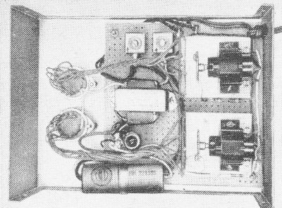
Parts placement for the underside of the Gamester chassis is shown above.
Another piece of the same spring wire serves as the contactor which rides on
the back of the gear as the motor turns. It is held in place by another wood screw
as shown and its pressure is adjusted so that it doesn't slow down the motor. It's
a good idea, too, to connect the 100,000-ohm resistor at this time, holding it in
place with a solder lug at each end. The resistors act as protective devices tor
the Nixies and must not be omitted.
Power Supply Assembly. The Nixie Gamester is a.c.-operated.
One low-cost transformer supplies the anode power for the numerals and the low voltage
for the motors. A full-wave voltage doubler consisting of SR1, SR2, and the dual
capacitor C1a/C1b comprise the anode power supply, while an inexpensive magnesium-copper
sulfide bridge rectifier without filtering takes care of the motor drive.
All parts, except the push button and the Nixie sockets, are mounted on a sheet
of perforated Bakelite. Wiring is completed outside the case and the finished assembly
secured to the case by a long machine screw and brass spacer in each corner.
Wiring the Sockets. After you punch two 1" holes where the Nixies
are to go, fasten the little glow tubes and their sockets in place with a 1 1/4"
machine screw through each socket-flange hole. (The diameter of the Nixie is 1.080"
so it cannot slip through the hole). In this way, only the face of each tube will
be visible through the hole and the display will be much more effective.
Be sure to mount the sockets with pins 1 and 8 in a vertical line, pin 8 nearest
the top of the panel. Pass a very short length (about 1/4") of the stripped end
of hookup wire through each of the small holes in the commutator segments and solder
to the copper faces carefully. Don't use too much heat. Trim the ends of the wire
off after the solder has cooled.
The actual wiring should be done in a random fashion. Don't connect segment 1
to the socket lug for display number 1, segment 2 for number 2, etc. The numbers
should follow each other haphazardly so that it will be impossible to force the
motors to stop at any given place. Note that no connection is made to either pin
1 or pin 8 on the socket and that the common anode connection is pin 2.
Testing
To be sure that your Gamester will play a fair game, run through the following
tests:
(1) Wiper contact. With power on, slowly rotate each gear by hand and observe
the corresponding Nixie. Only one number should glow for each contact of the wiper
on a given segment of the copper. If one or more numbers do not appear, bend the
wiper so that it makes firmer contact. If more than one number is displayed for
any single contact, it means that there is a bridge of copper between segments that
was not etched away. A bridge like this can be picked off with a sharp point and
the insulating groove cleared.
(2) Contactor. While each gear is manually rotated, observe the rear contactor
to be certain that it maintains electrical touch with the rear face of the gear
throughout the entire rotation.
(3) Motor spin. Motors should start instantly when the power is applied and should
spin at high speed. If they don't do this, reduce wiper and contactor pressure by
bending the wires back very slightly.
(4) Blankouts. The small contact surface of the wiper permits it to come to rest
occasionally between segments. When this happens, the corresponding Nixie will not
glow. Chances of both wipers blanking out on the same spin are very remote. You
should, however, run through a number of spins watching for this kind of thing.
If it happens too often, the wiper is catching on the edge of one of the segments
as a result of excessive wiper pressure. A single blankout provides a one-digit
readout and is desirable for most games in which the numerical sequence wanted runs
from zero to 99 with no numbers missing.
Posted December 15, 2022
(updated from original
post on 7/8/2012)
|