|
September 1974 Popular Electronics
 Table of Contents
Wax nostalgic about and learn from the history of early electronics. See articles
from
Popular Electronics,
published October 1954 - April 1985. All copyrights are hereby acknowledged.
|
One of the best ways
to learn about how something work is to build and operate it yourself. This article
from a 1974 issue of Popular Electronics magazine presents a voice scrambler that
exploits a simple spectral inversion
technique to create a mirror image of the original voice spectrum. Spectral inversion
occurs whenever the difference frequency is taken during a mixing process, so that
low frequencies are translated to the high end of the band and high frequencies
are translated to the lower end of the band. The result in the case of audio (voice)
is garbled sounding speech. It is probably the simplest form of scrambling that
is easily unscrambled, but it serves as a good learning tool. See the accompanying
secure communications article entitled, "Secrecy
Through Electronics."
Enjoy Private Messages with a Voice Scrambler
 Low-cost IC circuit makes messages unintelligible
without a similar unit. Low-cost IC circuit makes messages unintelligible
without a similar unit.
By Joseph B. Wicklund, Jr.
Would you like to be able to keep unauthorized people from listening to your
private communications? Thanks to recent advances in integrated circuit technology,
it is possible to build a low-cost voice scrambler that will make your message unintelligible
to anyone who doesn't have a compatible unscrambler. Of course, voice scramblers
have been around for many years, but most of them are too expensive or too difficult
to use (or both). This circuit is easy to build, is reliable, and can be used as
either the scrambler or unscrambler. How Scrambling Works. The block diagram in
Fig. 1 shows how the scrambler works. The incoming audio signal is filtered to remove
all frequency components above 3 kHz as shown at (A). The signal is then used to
modulate a 3.5 -kHz oscillator signal, with a linear four - quadrant multiplier
as the balanced modulator. The output (B) of the multiplier includes the sum and
difference frequencies between the two inputs. Another filter removes the sum frequencies
and any remaining 3.5 -kHz carrier, leaving only the difference frequencies as shown
at (C).
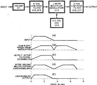
Fig. 1 - Block diagram and waveforms show how the scrambler works.
(A) is incoming signal; (B) is sum and difference; and (C) is output after filtering.
Unscrambling is shown in (D) and (E).
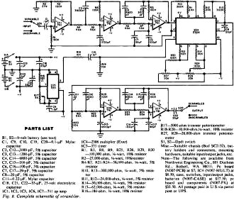
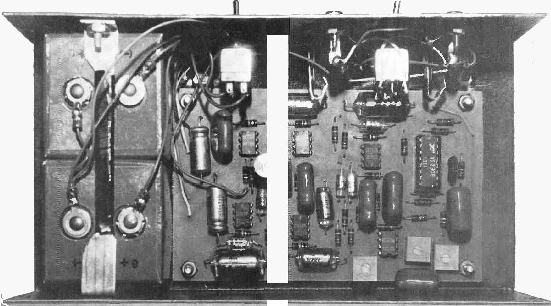
Fig. 2 - Scrambler / unscrambler circuit schematic.
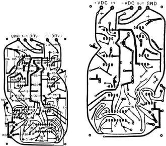
Fig. 3 - Foil pattern for scrambler / unscrambler is shown above
at right, component layout at left.
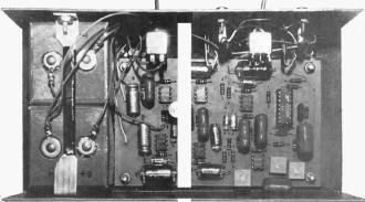
Photo shows how the prototype was assembled. Batteries are at
left, but an external supply can be used it desired.
It is interesting to note that, in the output, the voice channel from 300 to
3000 Hz is contained in a single sideband signal from 3200 to 500 Hz. It can be
recorded or transmitted like any other voice signal, but the frequency spectrum
of the output is an inversion of the input. (For example, an input frequency of
300 Hz is 3200 Hz in the output and an input of 2500 Hz is 1000 Hz in the output.)
The inversion thus makes the voice message unintelligible.
When the scrambled signal is coupled to the input of a similar unit, the signal
is re-inverted and the original audio comes out in unscrambled form as shown at
(D) and (E) in Fig. 1.
Circuit Operation
The complete schematic of the voice scrambler is shown in Fig. 2. Integrated
circuit IC1 is used as a high input impedance buffer amplifier to prevent loading
on the signal source. Resistors R2 and R3 control the gain of the buffer. An active
lowpass filter with a cutoff frequency of 3000 Hz is provided by IC2 and IC3. The
shape of the filter is controlled by the feedback components (R4-R7 and C2-C7) and
the circuit is designed to provide a four-pole Chebyshev filter characteristic with
1 dB of ripple in the passband and a sharp rolloff. Integrated circuit IC5 is a
stable squarewave oscillator operating at a frequency determined by R16, R17, and
C9. Potentiometer R17 is used to adjust the oscillator frequency so that two or
more units can be matched. The oscillator output is attenuated by resistors R18
and R19 and modulated by the output of IC3, the filtered input signal. The balanced
modulator is IC4. Trimpots R27 and R28 provide balancing adjustments for the modulator.
When they are properly adjusted, only the sum and difference frequencies of the
two inputs will appear at the output. Integrated circuits IC6 and IC7 form a lowpass
filter to pass only the desired output signal. The output of IC7 can be used to
drive load impedances as low as 2000 ohms. It can be used with most amplifiers,
for speaker applications, or a set of 2000 -ohm head phones.
Construction
To ensure that the active filters are properly tuned, it is recommended that
5% resistors and capacitors be used for the critical components (R4-R7, R21-R24,
C2-C7, and C12-C17). The gain -controlling resistors for the multiplier (R10-R13)
should also have 5% tolerances.
Although the circuit can be wired point-to-point on perforated board, it is preferable
to use a pc board such as that shown in Fig. 3. Be sure to observe the notch codes
on the IC's and the polarities of the electrolytic capacitors so that they are properly
installed. In using a pc board, note that 8-pin DIP 741 opamps are required. If
point-to-point wiring is used, other versions of the 741 (round, 14 -pin DIP or
dual) can be substituted.
Mount the batteries in holders in any convenient location in the chassis. If
desired, the power can be obtained from an external supply between ±6 and ±15 volts.
The supply voltage is not critical as far as circuit operation is concerned, but
the maximum input signal level and the overall gain will vary for different supply
voltages. The gain can be adjusted by changing the values of R3 (raising it to increase
the gain) and R18 (lowering it to increase oscillator signal level). The input and
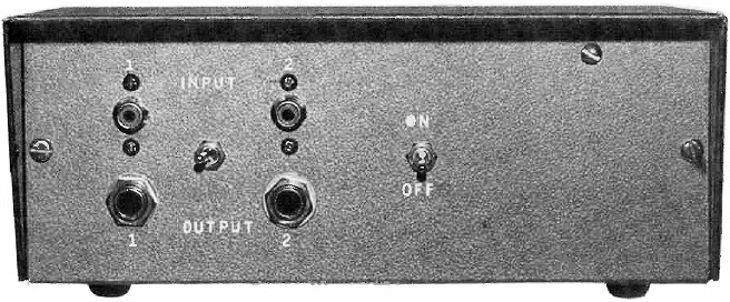
output connectors on the front panel must be chosen to suit the application. Adjustment.
For proper operation, the oscillator should be adjusted to 3500 Hz. If an accurate
counter or oscilloscope is available, R17 can be adjusted while monitoring the output
of IC5 (pin 3). An alternate method of adjustment based on the accuracy of the lowpass
filter can be used if necessary. With the input shorted to ground and R17 turned
fully counterclockwise, adjust R28 to get an output of 0.15 volts on an ac voltmeter.
Now adjust R17 until the output voltage falls to 0.026 volt. The oscillator is now
adjusted to approximately 3500 Hz.
To balance the multiplier, it will be necessary to adjust R27 and R28 while monitoring
the scrambler output with an ac voltmeter or a set of headphones. With no signal
input, adjust R28 for minimum output (near the middle of its range). To adjust R27,
it is necessary to disable the oscillator by shorting across capacitor C9. With
an input signal of about 1/2 volt (1000 to 3000 Hz), adjust R27 for minimum output
signal. The scrambler is now ready for use.
Use
A crystal microphone can be connected to the input of the scrambler with the
output (with unity gain) connected to the mic input of a tape recorder or transmitter.
If headphones are used, the scrambled signal is connected to the unscrambler. Alternatively,
the unscrambler can be connected between the recorder preamplifier and speaker amplifier
(or receiver detector and audio amplifier).
The multiplier portion of the circuit can be used as a single-sideband modulator:
The multiplier can be modified to operate with carrier frequencies as high as 5
MHz. Pins 13 and 14 of IC4 should be shorted to pin 4, with R10 through R13 removed,
a 5100 -ohm resistor connected between pins 4 and 15, and pin 2 connected to pin
16. With IC5 removed, the desired carrier signal can be coupled into pin 4 (using
about 1 volt). The output of IC4, from pin 15, can be coupled into a SSB filter
to remove the unwanted sideband.
The multiplier can also be used as a variable-gain amplfier, or remote volume
control. If the oscillator is removed, the gain of the multiplier can be controlled
by varying the dc level on pin 5 of IC4 from 0 to 5 volts. One way to accomplish
this is to include a 100,000 ohm potentiometer in series with a 100,000 ohm resistor
across the positive supply. Remove IC5, R18, and R19. Connect C10 from IC4 (pin
5) to ground. Connecting the wiper from the potentiometer to IC4 (pin 5) will provide
the desired variable voltage. For wide -band or hi-fi use, remove the two active
filters. A control range of 50 dB can be obtained with low distortion.
Posted September 23, 2019
|