|
|||||||||||||
 |
|||||||||||||
Put PEP in Your Antenna Tuner
|
|||||||||||||
Put PEP in Your Antenna Tuner  By Joseph W. Doherty, K2SOO By Joseph W. Doherty, K2SOO
The coupler you built last November grows up with just a few extra parts. If you built the pi-section receiver antenna coupler described in November POP'tronics ("Soup Up Your DX with an Antenna Tuner"), here is a worthwhile addition you can make at slight expense and in little time. If you have not yet built the coupler, you can put together the complete unit in one evening. It is sure to pay extra dividends in improved reception. As a matter of fact, this unit, which started out as a simple antenna tuner and grew into a preselector and signal booster, can make your old receiver practically jump right off the table.
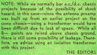
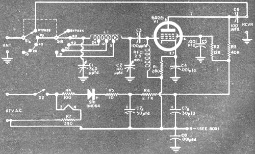
How It Works The pi-network coupler is the tuned grid circuit of the 6AG5 tube. An untuned plate circuit is used to prevent oscillation. The output is resistance-capacity-coupled and fed directly to the receiver input terminals where it may be peaked by the receiver input circuits, depending on design. Choke RFC1 maintains a high impedance to ground in the grid circuit of the amplifier, and provides a grid return circuit. Capacitor C8 provides an r.f, grounding path from the negative side of the power supply. Parts List CI-360-μμfd. variable capacitor Design Features This signal booster will provide amazing improvement even in a well-matched antenna system. There is a band selector switch position which allows you to bypass the coupler without having to disconnect the antenna and reconnect it to the receiver. The power supply is of the a.c./d.c. type. However, neither leg of the line is connected to the chassis, thus eliminating the shock hazard associated with power supplies of this type. The rectifier is a silicon diode #1N1084 which comes complete with mounting hardware and 10-ohm resistor in the Sarkes Tarzian Replacement Kit #M150. Any other type rectifier with a 20-ma. or higher rating may properly be substituted. To conserve space, a resistance-type line cord was used. Take care not to coil or bunch this cord, since it must be allowed to give off heat. Also, do not attempt to shorten it. The built-in resistor is 390 ohms "long." Construction Details. The original design was modified to accommodate the r.f. amplifier with minimum expense and fewest circuit changes. Follow this procedure. First remove the original Bypass jumper from S1a, S1b. Disconnect the lead to the junction of L1 and C2. Then disconnect the antenna input lead from S1a. Connect the antenna input lead to the wiper contact of S1b. Connect a lead from the 80-meter position on S1b to the S1a 80-meter position and S1a wiper. Now connect the Bypass lead from S1b to the ungrounded output terminal and, finally, connect the grid lead from C3 to the junction of L1 and C2. Since there is considerable gain in the amplifier, it is recommended that the input and output leads be kept well separated or oscillation may result. As an example of the gain obtainable, one station heard in the bypass position was read on the receiver S-meter at "S6." The preselector raised this same signal to 40 db over "S9," thus pulling it well out of the noise. The coupler should be grounded to a cold water pipe or similar good ground. If the receiver used is of the a.c./d.c. variety, connect the coupler output terminals to the receiver antenna terminals only. Tuning the Preselector Tuning is not difficult if you remember that C1 is the loading capacitor and C2 is the frequency-determining capacitor. There is some interaction between the two but, to keep it simple, adjust both alternately for the loudest signal. It is best to start out with C1 at maximum capacitance, tuning C2 until the signal is loudest. Keep in mind that the bandswitch must be in the proper position. Decrease the capacitance of C1 gradually until the signal starts to fade. Readjust C2 for the loudest signal. If the signal has increased, decrease C1 still further and repeat the process until the greatest signal strength is achieved. In most cases, a point will be reached where advancing C1 will cut the signal strength in spite of adjusting C2. This point is just beyond optimum coupling, which means that the antenna is over-coupled. At this point, rotate C1 in the other direction slowly while adjusting C2 through resonance until the optimum adjustment is found. Note: While we normally bar a.c./d.c. chassis projects because of the possibility of shock hazard, in this case - since the antenna preamp was built up from an earlier project on the same chassis - using a transformer would have been difficult due to lack of space. While all B -- points are raised above chassis ground, there is still some possibility of leakage. Therefore, we advise using an isolation transformer with this project. The Editors
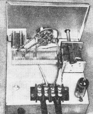
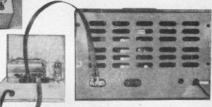
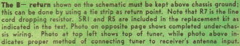
The B-return shown on the schematic must be kept above chassis ground; this can be done by using a tie strip as return point. Note that R7 is the line cord dropping resistor. SR1 and R5 are included in the replacement kit as indicated in the text. Photo on opposite page shows completed under-chassis wiring. Photo at top left shows top of tuner, while photo above indicates proper method of connecting tuner to receiver's antenna input.
Posted November 3, 2022 |
|||||||||||||
 |
|||||||||||||
|
|||||||||||||

|
||||||||||||||||||||||||||||||||||||


