|
November 1956 Popular Electronics
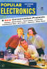 Table of Contents Table of Contents
Wax nostalgic about and learn from the history of early electronics. See articles
from
Popular Electronics,
published October 1954 - April 1985. All copyrights are hereby acknowledged.
|
This "R/C Triplex:
Three Channels on One Channel" article that appeared in a 1956 issue of Popular
Electronics magazine was written by a fellow who was well known in the
aeromodeling world at the time -
Claude McCullough. Claude won many titles in precision scale for both
control line (C/L) and radio control (R/C). As was the case with many R/C modelers of the
era, he did a lot of experimentation with transmitters, receivers, and
electromechanical devices used to move control surfaces. Rubber-band-powered
escapements dominated the field, but some servomechanisms were being developed
to provide a means for proportional control and/or a more powerful means of
multiposition control. As can be seen in the video I produced showing how a
typical
escapement worked, the output drove the airplane's rudder to either neutral,
full left, or full right deflections, with no position in-between. To actuate
the control, the R/C pilot pushed a button on the transmitter the number of times
required to affect the desired control movement. That made for somewhat jerky
flights, but it was a very popular setup. At some point people started adding
more positions via more pulses, which allowed the number of controls to be
expanded to rudder, elevator, and engine throttle, as reported here in this
article. It was still very crude by today's standards with precision
digital proportional R/C systems, but it
did enable more complete control over models and allowed scale types like
Mr. McCullough flew in competition to demonstrate behavior closer to the
full-size aircraft.
R/C Triplex: Three Controls on One Channel
 By Claude McCullough By Claude McCullough
To the R/C fan who has been flying single-channel models, the challenge of
multiple controls is an enticing one. The "Triplex" circuit shown here was
developed over a period of years and flown in a number of the author's models.
"Triplex" provides three controls using any ordinary single-channel R/C
receiver. Most "rudder-only" models may be easily modified to carry it.
The basic principle of this method is the use of a pulse system of
proportional control. Addition of extra control features is accomplished in an
uncomplicated manner. They are simple to maintain and also achieve a degree of
"fail-safe" operation.
The R/C transmitter is keyed in the usual pulse method by a mechanical or
electronic pulser, in which control stick movements vary the pulse length from
no signal at one end of the range to a steady signal at the other. For the
author's purposes, the movement of the stick is limited, so it doesn't quite
reach the extreme positions. Two push-button switches have been added as shown
in Fig. 1. One is a normally closed switch which gives "full off" when
depressed; the other is a normally open switch which gives "full on" when
depressed.
Fig. 1 - Control switch hookup for proportional pulser S5 and S6 (shown on top
of unit at right, which was built by the author) are normally closed for motor
control and normally open for elevator control.
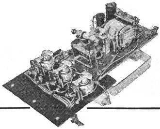
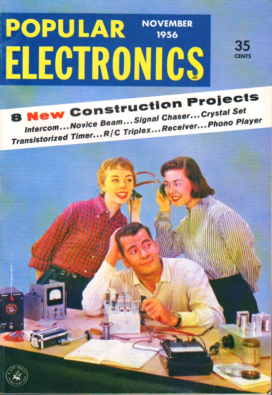
The receiving unit is mounted as an extension of the chassis of the McNabb
465-mc. receiver.
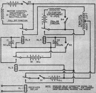
Fig. 2 - Schematic diagram of "Triplex" control system.
Component values are given in parts list above. See text for details of motor
control and elevator escapements, actuator and pulser. Note that all switches
are shown open in this diagram; they would be closed for normal operation.
When the pulsed signal is received by receiver relay RL1 in Fig. 2, the
twin-coil actuator displaces the rudder in proportion to the pulse rate. At the
same time, RL2 is keyed, which in turn keys RL3 and RL4. Relays RL3 and RL4 are
delayed for about one-half second by the 50-μfd. capacitors C1 and C2. A pulse
rate above 150 pulses per minute will cause relays RL3 and RL4 to remain closed.
If a full-off signal of about 3/4-second duration is sent via S5 (Fig. 1),
RL3 opens after a 1/2-second delay period and keys the motor control escapement.
If the motor control is an escapement-operated air-bleed valve, then holding the
full-off signal for several seconds will cut the motor. And since the continuity
of the actuator is broken, the rudder will be left in neutral position. This
prevents the model from a failure in flight due to the interruption of the radio
signal in some manner (such as transmitter failure or flying out of range).
Similar action occurs in RL4 when "full-on" is sent via S6 in Fig. 1 to
operate the elevator escapement. A four-position escapement is used in this case
to give half positions. The rudder control will give maneuverability while the
elevator is in any position.
When a full-on signal is sent, the rudder again falls to a neutral position
after the first 1/2-second. If you have interfering radio signals present,
simply switching off the elevator with S4 will allow you to fly with only rudder
and motor control. The single effect of an interfering signal will then be to
return the rudder to neutral.
Since the "Triplex" is to be added to your present equipment, the method of
mounting and installation is up to you. The photo shows a McNabb Citizenship
465-mc. receiver, with the extra components mounted on a Micarta extension to
the chassis.
Any sensitive relay with coils of 5000-10,000 ohms can be used for RL3 and
RL4 with the delay circuits shown; I used the Neomatic 7250-ohm subminiature
type in this original unit. It may be necessary to adjust the value of
capacitors C1 and C2 and the spring tension of the relays to give the required
delay. The keying relay in this circuit is a Neomatic with a 300-ohm coil,
employed in conjunction with an actuator using 6 volts through 20-ohm coils. Be
certain that the keying relay will close at the lowest voltage used to operate
the actuator.
The escapements will determine battery voltage for the elevator and motor
controls. Do not employ the same battery for both escapements or tap into the
actuator battery. Use a 15-volt Eveready #411 battery or a one-ounce equivalent
to power the delay relays. I recommend a twin-coil activator and a fully
variable pulser. Since an elevator is a much larger load than a rudder, use a
heavy-weight escapement and try balancing the elevator.
All of the components may be purchased from firms which specialize in R/C
equipment.
Parts List
B1 - 15 volt hearing-aid battery (Eveready #411 or one-ounce equivalent) -
see text for other battery voltages
C1 , C2 - 50-μfd., 25-d.c.w.v. electrolytic capacitor (Aerovox Bantam SRE)
RL1 - Receiver relay (part of receiver)
RL2 - Neomatic or similar subminiature relay, about 300 ohms
RL3, RL4--Neomatic or similar subminiature relay, 5000 to 10,000 ohms
S1, S2, S3, S4 - Miniature slide switches
S5 - Push-button switch, normally closed
S6 - Push-button switch, normally open
Posted January 24, 2022
|