|
October 1958 Popular Electronics
 Table of Contents Table of Contents
Wax nostalgic about and learn from the history of early electronics. See articles
from
Popular Electronics,
published October 1954 - April 1985. All copyrights are hereby acknowledged.
|
Commercially available test
equipment for hobbyists in the 21st century is pretty high quality at a relatively
low price, so the motivation for buying parts and building your own RF power meter
has to be driven not by cost, but by a desire to gain the experience. This 1958
Popular Electronics magazine article
presents a simple RF power meter that can be built for about $25 worth of parts.
All the parts should be readily available except for the Raytheon CK-721 (or
CK-722)
germanium PNP transistor. The
2N3906
and the 2N2907
have been suggested as replacements, but some changes in the biasing resistors might
be required.
Simple R.F. Meter
 By Charles J. Schauers By Charles J. Schauers
Measure r.f. output of the transmitter in your ham shack ... or use this meter
in -a dozen other ways
This inexpensive r.f. indicator has a wide variety of uses around the ham shack
or mobile radio installation. It can act as an absorption frequency meter (if calibrated),
a field strength meter, neutralization indicator, or modulation monitor with phones.
However, the main job of the model shown is to indicate proper antenna loading for
my "minified" mobile transmitter.
It is relatively simple to put together, and nearly any low-priced transistor
will work well. However, for maximum sensitivity, a transistor with a beta (current
amplification) of .between 25 and 45 should be used.
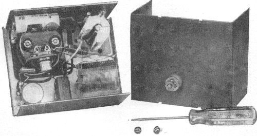
Construction
A 3 3/4" x 3" x 2 1/8" aluminum chassis houses all parts. The coil (L1) is tapped
and connected. to switch S1 before installation in the box to facilitate soldering.
Then the coil is cemented to the box by its plastic support.
Care should be taken in soldering the crystal diode (CR1) into the circuit by
"heat sinking" the connections with a pair of long-nose pliers. A socket should
be used for the transistor.
Fasten the 1 1/2-volt cell to the chassis with household cement. With normal
use, it should last almost its shelf-life.
After the unit is turned on, zero the meter with potentiometer R3 in the collector
circuit. Attach a small wire to the input binding post on the rear of the box which
feeds r.f. to the tuned circuit, and you are in business.
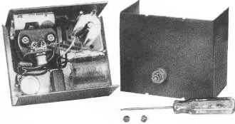
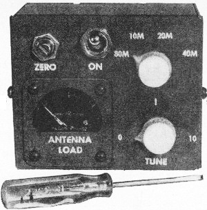
The simplicity of the r.f. meter circuit (see schematic below)
makes for ease of layout on the chassis (above). Number of turns tapped on L1 for
each band is indicated on the schematic. Finished meter is shown at top.
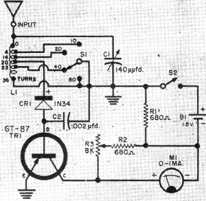
PARTS LIST
B1 - 1.5·volt D cell
C1 - 140·μμfd. miniature variable capacitor
C2 -
0.002·μμfd. mica capacitor
CR1 - Crystal diode (Sylvania 1N34 or equivalent)
L1 - #24·wire, 1"·diameter coil (Airdux 832T or B&W
3016 - 32 turns per inch, tapped as shown in
schematic)
M1 - 0-1 ma. d.c. meter
R1, R2 - 680·ohm, 1/2·watt resistor
R3 - 6500-10,000 ohm slotted shaft potentiometer
S1 - 1-p., 4-pos. rotary
switch
S2 - S.p.s.t. toggle switch
TR1 - Transistor (General Transistor
GT·87 or GT-88
or Raytheon CK·721)
1-Aluminum chassis box (LMB·135)
Applications
If the device is to be used as an absorption frequency meter, it can be calibrated
with a heterodyne frequency meter coupled to the input post through a small (about
500-μμfd.) capacitor.
A 2-1/2" length of wire is sufficient for r.f. pickup when checking
oscillator, doubler or buffer and final amplifier stages of a transmitter.
When using the indicator as a field strength meter to adjust a beam antenna,
the pickup wire length will depend upon the distance from the antenna and how much
power is being applied from the transmitter's final amplifier. Usually, a 2" piece
of wire will afford sufficient pickup at 100 feet with the average low-power transmitter
when the device is hand-held.
To provide some attenuation of very strong signals, the indicator can be used
harmonically. Set the bandswitch to 40 meters when you want to measure carrier strength
on 80 meters.
As a means for tuning mobile or fixed transmitters (especially those employing
pi-output-networks), this unit enables one to determine very quickly if the antenna
and not the pi-network is taking the load. For mobile operation, the regular auto
broadcast antenna can be used for signal pickup. However, the device should be harmonically
operated as described above because of the strong signal present. If the auto antenna
is not used, try a small piece of insulated wire taped to the inside of the front
bumper, connected with shielded wire to the indicator.
If you are interested in monitoring your modulation, a pair of magnetic phones
can be connected in the collector circuit of the transistor. The meter is disconnected
(as well as the top of the balancing potentiometer) and the phones are connected
between battery minus and collector.
How It Works
Radio frequency energy tuned by L1-C1 is applied to diode CR1. The rectified
current then takes a path through the base-emitter circuit of transistor TR1.
Current amplification occurs and is read by the 0.1 milliammeter. Capacitor C2,
connected between the transistor base and ground. bypasses the radio frequency.
The greater the strength of the r.f. signal picked up, the higher the reading on
the meter.
Posted November 18, 2022
(updated from original post on 9/19/2011),
|