|
August 1956 Popular Electronics
 Table of Contents Table of Contents
Wax nostalgic about and learn from the history of early electronics. See articles
from
Popular Electronics,
published October 1954 - April 1985. All copyrights are hereby acknowledged.
|
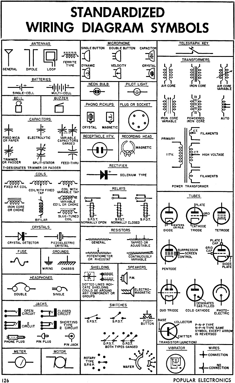
When this "Standardized Wiring Diagram Symbols
& Color Codes" feature appeared in a 1956 issue of Popular Electronics magazine,
semiconductors were just coming into common use. Therefore, only the simplest
components like a diode and bipolar junction transistor (BJT) are included. In fact, the only two
types of diodes shown are vacuum tube and selenium. The semiconductor diode is
labeled as a crystal rectifier. There is no light emitting diode (LED), field
effect transistor (FET), metal oxide semiconductor FET (MOSFET), integrated
circuit (IC), or other commonly used modern device. Note also that the "Receptacle 117V" does not
show a safety ground connection. The "Vibrator" was a device commonly used to
convert direct current (DC) to alternating current (AC). About the only people
who will find a use for this information are those who service and/or restore
vintage electronic equipment, but it's still a good thing to make available for
historical purposes.
Standardized Wiring Diagram Symbols & Color Codes
 Wiring Diagram Symbols Wiring Diagram Symbols
The standardized wiring diagram symbols chart has been updated recently to reflect recent additions
of semiconductor components, including the solid state diode and transistors. Notice the similarity
between these symbols and many of the ones in the
ARRL Handbook chart.
Resistor Color Code
RETMA Color Code Chart
The ohmic value of a resistor can be determined by means of the color code. There are two standard
methods of indicating this value.
In Fig. A. the body (A) and end (B) indicate the first and second digits of the value while the dot
(C) indicates the multiplier to be used. The tolerance of the unit is indicated by the end color (D).
For example. if the body (A) is green the number is 5; if the end (B) is grey the second number is 8.
If the dot (C) is red the multiplier is 100 or two zeros should be added. The resistor is then a 5800
ohm unit. If the end (D) has no color, the tolerance is ±20%.
 In Fig. B, the first
two stripes indicate the first two digits; the third stripe the multiplier; the fourth stripe the tolerance.
Thus, if stripe (A) is green, (B) is grey, (C) is red, and (D) is silver, the resistor is a 5800 ohm, ±10%
unit. In Fig. B, the first
two stripes indicate the first two digits; the third stripe the multiplier; the fourth stripe the tolerance.
Thus, if stripe (A) is green, (B) is grey, (C) is red, and (D) is silver, the resistor is a 5800 ohm, ±10%
unit.
Capacitor Color Code
Capacitance is given in μμfd.
 Colors have same values as on resistors, except as indicated
in tables. Colors (A) and (B) are for first two digits; (C) is for multiplier. (D) is for tolerance.
(E) and (F) give voltage rating in hundreds of volts; (E) is used only for ratings less than 1000 volts,
(E) and (F) for first two digits of ratings 1000 volts or more. Values of colors for (E) and (F) are
same as in resistance values. (G) is class or characteristic of capacitor. (H), (I), and (J) give temperature
coefficient. (G), (H), (I), and (J) are not listed in the tables, since this information is seldom needed
by the average home builder. Colors have same values as on resistors, except as indicated
in tables. Colors (A) and (B) are for first two digits; (C) is for multiplier. (D) is for tolerance.
(E) and (F) give voltage rating in hundreds of volts; (E) is used only for ratings less than 1000 volts,
(E) and (F) for first two digits of ratings 1000 volts or more. Values of colors for (E) and (F) are
same as in resistance values. (G) is class or characteristic of capacitor. (H), (I), and (J) give temperature
coefficient. (G), (H), (I), and (J) are not listed in the tables, since this information is seldom needed
by the average home builder.
Posted January 27, 2023
(updated from original post on 9/26/2016)
|