|
December 1974 Popular Electronics
 Table of Contents Table of Contents
Wax nostalgic about and learn from the history of early electronics. See articles
from
Popular Electronics,
published October 1954 - April 1985. All copyrights are hereby acknowledged.
|
There is no such
thing as too many articles on the subject of standing wave ratio. Standing
waves were known and studied long before their behavior in transmission lines
was of concern. Although the Wikipedia entry for standing waves credits
Michael Faraday for
first noticing them, undoubtedly centuries prior to that scientists like
Archimedes,
Isaac Newton, and
Descartes observed
and studied standing waves in ropes, vines, water, and other media. Author Carl
Drumeller went into a fair amount of detail with his description of the
phenomenon and the mathematical treatment of it, although he avoided the
application of complex numbers lest he scare away those unfamiliar with them (a
wise decision). This is one of the rare articles where voltage, current, and
power standing wave descriptions are provided.
VSWR: What it is. How it affects communications. How and when
to take corrective steps.

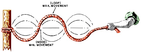
Fig. 1 - Standing waves on a rope. Such waves are generated by
the combination of travelling waves headed in opposite directions.
By Carl C. Drumeller
SWR is a term used often in amateur and CB communications. Usually, it sounds
as if the conversants were referring to an electromagnetic "bogeyman" which wreaks
all manner of havoc in communications systems. Many strange powers are attributed
to SWR, including the ability to destroy output tubes or transistors, make proper
loading of transmitters difficult or impossible, neutralize a large portion of the
output power, cause distortion, and even cause coaxial cable to heat up and melt
its insulation.
Here's what SWR really is, how it affects communication systems and what can
be done about it.
What It Is
SWR is an abbreviation for Standing Wave Ratio, and comes in three varieties:
Voltage Standing Wave Ratio (VSWR), Current Standing Wave Ratio (CSWR), and Power
Standing Wave Ratio (PSWR). It is defined as the ratio of the maximum parameter
(voltage, current, or power) to the minimum, when sampled along a length of transmission
line. Why do waves "stand" on a line? Let us consider a typical transmitter installation.
The transmitter sends a train of sine waves down the transmission line (the radio
"hose" which carries power toward the load). If the impedance of the antenna is
the same as the output impedance of the transmitter and that of the line, then the
impedance of the entire system is constant, and since V = I x Z (voltage equals
current times impedance), the effective voltage and current are constant along the
line, the maxima equal the minima, and the SWR is one, or as commonly said "one
to one."
However, if the impedance of the antenna is different from the transmitter output
impedance and that of the line, the wave train, which was "used" to the V = I x
Z relationship of the line, experiences a new relationship at the abrupt change
of impedance. In order to fit within the constraints of the laws electromagnetic
waves obey, some of the power is sent back into the line, and a new wave train appears
heading down the line toward the transmitter. When two waves headed in opposite
directions meet, the result is a wave which stands still on the line. You can verify
this with a simple experiment (see Fig. 1).
Tie a rope or string to some solid, stationary object (a tree or post will do).
Grasp the free end and start waving the rope up and down. You are now generating
a train of waves down the rope, much in the way that a transmitter sends waves down
a transmission line. When the waves reach the point where the rope is anchored,
they experience a new condition - the post can't allow them to propagate, since
it is a stationary, inflexible object, so the waves are reflected and propagate
back down the length of the rope. This situation is analogous to the termination
of a transmission line with an impedance different from that of the line. You will
see a wave appear on the rope that does not move. It is generated by the combination
of the forward and reflected eaves, and is called a standing wave. The points on
the rope that appear to be free of vibration are called nodes, and the points of
maximum vibration are called loops or antinodes.
What SWR Does

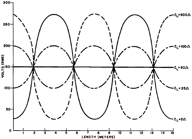
Fig. 2 - Voltage measured along a 50-ohm transmission line fed
with 450 watts of 20-MHz r-f when connected to various loads. Voltage Standing Waves
are generated when the line impednce is mismatched.

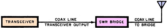
Fig. 3 - Typical SWR bridge installation. Bridge is placed in
series with coaxial line along the way to the antenna at a convenient spot.
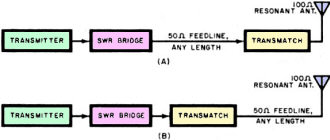
Fig. 4 - Transmatch configurations. Matching networks are adjusted
to present a 50-ohm impedance to the transmitter. A mismatch can still appear at
the antenna depending on where the transmatch is inserted.
When an impedance mismatch generates a standing wave on a line, the voltage and
current distribution along the line is upset. In Fig. 2, we have plotted the voltage
between the conductors of a transmission line as a function of the length of the
line. A family of curves appears when various impedances are used to terminate the
line. When ZL (load impedance) is 50 ohms, we see that the effective
value of the voltage along the line remains a constant 150 volts. This figure is
determined by the equation P = V2/Z, where P is 450 watts and Z is 50
ohms. The maximum and minimum voltage (Vmax and Vmin) are
both 150 volts, and the SWR, defined as Vmax/Vmin is 150V/150V,
or 1:1 (Spoken as "one to one").
When a 25-ohm load terminates the line, a standing voltage wave appears on the
line. V. equals 100 volts, and appears at the transmitter end of the line, and at
integral multiples of one-half of a wavelength. Vmax is 200 volts, and
appears at odd multiples of one-quarter wavelength. The SWR is 200V/100V, or 2:1.
When a 100-ohm load is connected to the line, the values of Vmax and
Vmin are the same as the case above, except that the 200-volt Vmax
appears at the transmitter end of the line, and at whole multiples of a half-wavelength.
Vmax (100V) appears at odd multiples of a quarter-wavelength.
A more extreme case is shown when a 500-ohm load terminates the 50-ohm line.
In this case, Vmax equals 272 volts, and it appears at the transmitter
end of the line. Vmin, 27.2 volts, appears at odd multiples of a quarter-wavelength.
The SWR is 272V/27.2V, or 10:1. We see that a large voltage is found at the transmitter-transmission
line connection. This voltage may exceed the voltage rating of the active device(s)
in direct-coupled final amplifier and destroy it. Transistors are much more intolerant
of voltage overloads than tubes, and most will be destroyed instantly under such
conditions. Even hardy vacuum tubes will blow when subjected to prolonged operation
under these conditions.
If we terminate the line with a 5-ohm impedance, we note a Vmin of
27.2 volts, at the transmitter feed point, and at integral multiples of a half -
wavelength, and a Vmax of 272 volts located at odd multiples of a quarter
wavelength. As above, the SWR is 10:1.
High SWR will cause certain points along the transmission line to have a high
r-f potential difference between conductors. In VHF or UHF systems, depending on
the power rating of the cable, transmitter output power, and the SWR, this potential
difference will be great enough to cause hot spots due to dielectric losses, or
even arcing between conductors. Hot spots appear at current maxima in HF systems
due to I2R effects. High SWR can make transmitter tuning very critical,
necessitating large changes in control setting for a slight change in frequency.
This occurs because the reactive effects of a mismatched line change with frequency,
as does SWR.
Reactance, for the sake of review, is the opposition to ac offered by an inductance
or capacitance. It is expressed in ohms, but is not a resistance - pure reactance
does not dissipate any power, but returns a portion of the power to the generator
during each cycle. A line not terminated in its characteristic impedance behaves
in this manner by setting up a backward-travelling wave train. Equal amounts of
capacitive and inductive reactance cancel each other out. For example, 25 ohms of
inductive reactance combined with 25 ohms of capacitive reactance produce a net
reactance of zero ohms.
The tuning and loading controls of a transmitter introduce amounts of inductive
or capacitive reactance to cancel out the reactive properties of the line. If these
adjustments are made correctly, the transmitter sees a purely resistive load. Impedance,
the term we have used to describe the relationship between voltage and current in
transmission lines and loads, is the phasor or vector sum of the resistance and
reactance in a circuit.
If the characteristic impedance of the line (Z) and the impedance of the load
(ZL) are purely resistive, then the SWR may be obtained from: SWR = RL/RO
for RL>RO and SWR = RO/RL for RO>
RL. For example, if RO is 50 ohms, and RL is 25
ohms, the SWR is 50 ohms/25 ohms, or 2:1.
So far, we have not mentioned power loss as one of the seriously harmful effects
of SWR on a communications system. Many operators look upon output power as a commodity
more precious than gold, and develop ulcers at the thought of losing any of it to
resistive or reactive elements in the system. While it is true that SWR indicates
that a part of the transmitter output is not reaching the antenna, the amount of
power lost in most situations does not justify the degree of concern it generates.
How can we determine what fraction of the power is being returned to the transmitter?
A quantity called the reflection coefficient, ρr, gives this information.
The reflection coefficient is defined as:
ρr = (ZL - ZO)/((ZL
+ ZO) = (SWR - 1)/(SWR + 1)
If a line has an SWR of 2:1, then the reflection coefficient is (2 - 1)/(2 +1),
or 1/3. This means that 1/3 of the voltage wave sent down the line by the transmitter
is returned. Since the power P equals V2/Z, the fraction of the power
returned is equal to ρr2, or 1/9. The portion of the power
which is delivered to the antenna (neglecting line losses) may be expressed as the
ratio of P, the power which reaches the load, to Pm the power which would
reach the load if the system were matched, by the formula:
P / Pm = (1 - ρr) = (4
x SWR) / (SWR + 1)2
The power loss with a 2:1 SWR is not great (11% or ½ db). The human
ear, or most S meters for that matter, could not tell the difference. Only when
the SWR reaches 5:1 do we note a reflection of one half of the transmitter output
power. This may sound like a large power loss, but it will only register as a 3-dB
decrease in signal strength on an S meter. When such a meter is properly calibrated,
one S unit equals 6 dB, so the decrease in signal strength caused by a 5:1 SWR will
amount to only one half of an S unit. Many operators would be hard pressed to detect
the differences using just their ears. However, as we have noted, this does not
mean you should allow such a state of affairs to exist.
How to Measure SWR
If, at a certain point along the transmission line, we sample the magnitude of
the forward-going voltage wave, and then the reflected voltage wave, we can take
the ratio of these magnitudes (forward to reflected) and obtain the VSWR. We could
also sample power and obtain the PSWR. Devices which pass energy in only one direction
are called directional couplers. An SWR monitor can be made by inserting two directional
couplers into the line, and connecting them to meters which will monitor the magnitudes
of the parameter we choose to measure.
There are many units available which will monitor SWR. The most common type is
called a reflectometer or SWR bridge. Atypical reflectometer includes two jacks,
to which cables from the transmitter output and the antenna are connected, a sensitive
meter with a direct SWR scale calibration, a sensitivity control which is used to
calibrate the unit, and a selector switch which connects the meter to one of two
directional couplers. Prices of these reflectometers are usually $15 to $20, and
the following comments pertain only to these types of reflectometers, not the more
expensive, well engineered units.
The Truth About Reflectometers
Reflectometers of this type are adequate for most amateur and CB purposes, but
there are a few realities that must be recognized before attempting to use one and
obtain meaningful results. Reflectometers are designed to give a relative indication
of SWR, but accuracy varies from unit to unit, and they are easily "fooled" into
giving readings which do not truly reflect the conditions on the line.
If it were possible to connect the reflectometer to the line at any point (which
is not convenient, since the line has to be interrupted to insert the reflectometer),
we might get. a wide range of values of SWR from the meter. Does this mean that
the SWR varies from point to point? No, it merely means that the line at certain
points "hides" the true value of SWR from the reflectometer. If you already have
an SWR Bridge, and have done some antenna experimentation, you might have encountered
the following situation.
After installing a new antenna, a feedline is connected and run down to the transmitter.
At the transmitter input, you connect the bridge and tune up the transmitter. After
adjusting the bridge, you read an SWR of 1.5:1. Then, for one reason or another,
you permanently move the transmitter and have to add on a piece of transmission
line, or trim the line to fit the new operating location. The next time you tune
up, you find you have an SWR of 3:1. "What's going on here?" you might wonder, since
frequencies haven't changed or the antenna altered.
The answer to the higher SWR reading lies in the properties of a mismatched transmission
line. Not only does a mismatch set up voltage, current and power standing waves,
but an impedance one as well. If the mismatch is severe, but the transmission line
is an odd multiple of a quarter-wavelength, the reactive effects of the line are
hidden from the reflectometer and the transmitter (if the meter is inserted into
the line close to the transmitter). In the first case, the line was close to this
special length. But when the length was changed the true situation on the line was
no longer hidden.
You may have noticed that some mobile antennas come with a length of transmission
line attached, and the manufacturer's instructions clearly advise that the line
not be cut, but that the excess be rolled up and stowed somewhere along the path
the line will follow. This length is a quarter-wavelength or an odd multiple. Such
antennas normally operate with a high SWR, but the length of the line is chosen
to hide this from the transmitter. As you can see, you can't put absolute faith
in a reflectometer reading.
There is an easy way to make sure that the SWR reading that the reflectometer
is showing you is a close approximation of the actual SWR. Fig. 3 shows a typical
installation configuration for a reflectometer.
The reflectometer may be inserted at any point along the transmission line, but
as noted it may give different readings at various points. Which one is the true
SWR? If the bridge is located at the antenna feed point, with the antenna connected
directly to the output jack of the SWR bridge, then the reflectometer will indicate
the true SWR on the line. This is an inconvenient place to connect the bridge, however,
since most antennas are mounted a considerable distance away from the transmitting
equipment, out of the operator's view.
Because of this difficulty, almost all SWR meters are inserted into the line
near the transmitter or the operating position. If this is the case at your installation,
you should connect a piece of transmission line, using a dual - female adapter and
properly installed coaxial plugs between the line and the bridge. The extension
should be less than Ye wavelength long. After installing the extension, tune up
the transmitter (legally!) and note the SWR. If it has changed radically from the
previous reading, you can be certain that a high SWR exists on the line and that
any low readings are false. The test may also be run by trimming the feed-line,
but usually this is inconvenient, since any cuts in the cable are permanent.
What to Do About SWR
Now that you've made sure your SWR bridge is telling the truth and you find that
you have an SWR of 3:1, what should be done? Should you fool around with the feedline
or antenna or just leave things as they are? The answer depends on the type of feed
line you have and the limitations of your transmitter.
If your transmitter is built to withstand "infinite SWR," then you can tolerate
such a mismatch, and the power lost will not seriously degrade the strength of your
signal. However, if you are using a transmitter which can take a maximum SWR of
2:1 (consult the spec sheet for this), and/or you are running an output close to
the maximum power rating of the coaxial feedline, then you should take steps to
make the mismatch less severe or make things appear that way.
Perhaps the easiest way to do this, if the load is highly reactive (a mini-whip
or other loaded antenna), is to trim the length of coaxial feed line for a tolerable
sending-end impedance. This does not really solve the mismatch problem, however.
The best way to correct a mismatch is to adjust the antenna or the feed line
impedance for a good SWR. Most commonly available transceivers and transmitters
are designed to work into 50- to 75 -ohm loads, and are tolerant of a maximum mismatch
of 2:1. The range of impedances that the transceiver can work into is therefore
from 25 to 150 ohms. If you are operating on one band only, 11 meters or one of
the amateur bands between 7 and 30 MHz, you can use a simple dipole for edge-to-edge
coverage. The maximum SWR should be 2:1, although it varies with the height above
ground.
Most verticals can also cover an entire band with the same range of SWR. There
is one trick to the successful operation of all vertical antennas. To obtain a decent
SWR and efficient radiation, a good ground system must be used. If the vertical
is roof-mounted, a radial system using at least five quarter-wave wires must be
installed. The radials should droop slightly toward the roof.
A good radial system will include as many as 200 or more radial wires. Since
copper wire is expensive these days, it is economically wise to use aluminum radials
in your ground system.
By adjusting the radial system of a vertical, a dipole's height above ground,
or a "gamma match" on a beam, you are changing the antenna feed-point impedance
to a value which is closer to the characteristic impedance of the feed line, thus
reducing the mismatch. This is the most effective way to reduce SWR.
There is another approach, however - matching networks or "transmatches." These
devices act as variable impedance transformers, converting a wide range of loads
to the ideal 52 ohms. Transmatches also tune out any reactance that the feedline
may present to the transmitter, making it easier to load up the output stage. If
a transmitter has a pi-network output, or a transmatch is used, SWR does not contribute
to a power loss in the system. The network is adjusted to present the right amount
of reactance necessary to cancel that at the load. Any power that is reflected down
the line from the load will simply be rerouted back to the load. A forward-power
measurement would show a greater amount than the transmitter output due to this
compensation.
Figure 4 shows two configurations for transmatches. At "A" we see that a transmatch
has been installed at the antenna end of a stretch of 50-ohm transmission line.
A 100-ohm resonant antenna has been connected directly to the output of the transmatch:
If we adjust the matching network to step down the 100-ohm impedance to a 50-ohm
one, the SWR bridge will read 1:1. This is a true reading, since the transmitter
output impedance, the line characteristic impedance, and the transformed antenna
impedance are all 50 ohms. There are no standing waves on the line.
At "B" we have a second case. The transmatch is located at the transmitter end,
right after the SWR bridge. Between the transmatch and the antenna, whose impedance
is 100 ohms, a 50-ohm transmission line is connected. If we adjust the transmatch
to give a 1:1 SWR reading on the reflectometer, do we have the perfectly matched
condition at "A"? No, we don't! Although the transmatch fools the transmitter into
thinking so, by presenting a 50-ohm impedance for the transmitter output, we still
have an SWR on the transmission line due to the feeder/antenna mismatch.
When can SWR be ignored? If you are running output power well below the maximum
rating of the feedline, and do not exceed the mismatch toleration of the transmitter,
then you can safely ignore the SWR. If transmitter tuning becomes balky, feedlines
heat up, or output amplifiers pop, then you should put into action one of the above
-mentioned plans.
Try adjusting the antenna first. If you still have problems, make sure your transmission
line and its connectors are in good shape. An antenna matcher should be used as
a last resort (for coaxial lines). Above all, don't listen to the old wives' tales
about SWR!
Posted January 27, 2022
|