October 1960 Popular Electronics
 Table
of Contents Table
of Contents
Wax nostalgic about and learn from the history of early electronics. See articles
from
Popular Electronics,
published October 1954 - April 1985. All copyrights are hereby acknowledged.
|
If you are looking for
a very thorough treatise on transformers, from AC line frequency up through audio
and RF frequencies, but without a lot of formulas to distract you, then this article
by Ken Gilmore is it. He begins with the fundamentals of a current setting up a
magnetic field, talks about mutual coupling and induction, step-up- and step-down
transformers, autotransformers, iron and laminated core transformers, multi-tap
voltage and impedance matching transformers, and even touches on the mage-size transformers
in electrical distribution system substations. Transformers fundamentally work the
same way today as they did when first invented in the 1830s. Equations for simulations
have been refined to the nth degree, but for the vast majority of mankind this article
will suffice to provide a better-than-a-layman's knowledge of the principles.
The Transformer
By Ken Gilmore
A fundamental coupling device, the transformer is one of electronics' most capable
magicians - here's what's behind its electrical sleight-of-hand and how it performs
its multitude of valuable tricks.
What the Transformer Does
The electrical power that makes your light bulbs glow, runs your refrigerator,
and operates your hi-fi set comes into your home at a potential of about 115 volts.
Yet if you were to climb the utility pole outside and measure the voltage there,
it could turn out to be as high as 6000 volts. If you kept on climbing poles at
other places around town, you might find voltages as high as 120,000 volts!
Even in your home, some appliances - air conditioners, clothes dryers, electric
ranges, and other heavy-duty equipment - may operate at 230 volts instead of the
usual 115 volts. And if you probe into your television set, you'll find an even
wider voltage range. For although your TV draws its power from the wall plug - and
power there is at 115 volts - your set has the ability to change this voltage into
a number of different values, so that each tube and circuit can operate under the
exact conditions it likes best. Consequently, in some places, you will find values
as low as one or two volts; in others, values as high as 15 or 20 thousand volts.
Electric power, one of our most useful servants, becomes tremendously more useful
when we can change it at will to dozens, or even hundreds, of different voltages.
Fortunately, we can make these changes easily and economically with a device known
as the transformer.
Transformers are all around us. One - the gadget about the size of a large garbage
can hanging near the top of utility poles - changes the 6000-volt transmission-line
power into the 115 and 230 volts you need. Another - this one about as big as a
flashlight - takes 6 or 12 volts from your car's battery, and changes it into the
10,000 or more volts needed to fire your spark plugs. Still another - a square can
a little bigger than your fist - channels high-fidelity electrical signals into
the speakers of your hi-fi set.
We'll talk more about these special applications - and others like them - a little
later. Right now, let's get down to the business of seeing just how a transformer
goes about performing this valuable electrical sleight-of-hand-changing one voltage
into another.
How the Transformer Works
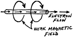 When an electric current flows in a wire,
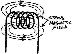
a weak magnetic field is set up around it. If we twist the wire into a coil, the
weak field around each turn of the wire is reinforced by the fields around the other
turns; the result is a much stronger field. When an electric current flows in a wire,
a weak magnetic field is set up around it. If we twist the wire into a coil, the
weak field around each turn of the wire is reinforced by the fields around the other
turns; the result is a much stronger field.
If an a.c, current flows in the coil, the magnetic field builds as the current
flows in one direction; dies down, or decays, as the current returns to zero; then
builds in the opposite polarity as the current flows in the other direction. You
can think of the building and decaying magnetic field as a pulsing, invisible force,
expanding and contracting as the current reverses its direction of flow. As the
field builds and decays, the magnetic flux lines (the circular lines in the diagram)
cut back and forth through the coil.
 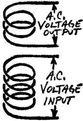 Now suppose we put another coil of wire
next to and in line with the first, although not actually touching it. As the magnetic
field expands and contracts, the flux lines will cut back and forth through the
second coil as well as through the first one, and a voltage will be induced in the
second coil. This is called "mutual induction," and is the basis of all transformer
action. Because of this property, a simple transformer can be made - and many are
- simply by placing two coils of wire close together and applying an alternating
current to one of them. Now suppose we put another coil of wire
next to and in line with the first, although not actually touching it. As the magnetic
field expands and contracts, the flux lines will cut back and forth through the
second coil as well as through the first one, and a voltage will be induced in the
second coil. This is called "mutual induction," and is the basis of all transformer
action. Because of this property, a simple transformer can be made - and many are
- simply by placing two coils of wire close together and applying an alternating
current to one of them.
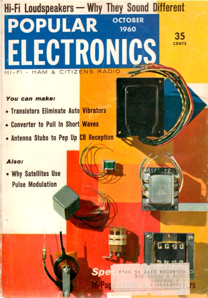
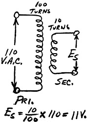
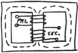
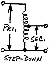
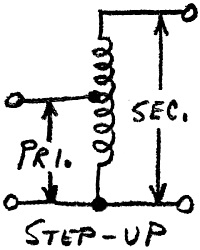
The main value of a transformer lies in the fact that the ratio of the voltages
in the two coils can be controlled by the number of turns of wire in each. To put
it another way, if the secondary (the coil into which voltage is induced) has ten
times as many turns of wire as the primary (the coil across which the original voltage
is applied), then the secondary voltage will be ten times the primary voltage. In
such a case we have a step-up transformer.
On the other hand, if the secondary has only one-tenth as many turns as the primary,
the secondary voltage will be one-tenth the primary voltage, and we have a step-down
transformer.
Efficiency
  In the above calculations, we have assumed
that all magnetic lines of flux, as they expand and contract, cut all turns of the
transformer. The magnetic coupling in such a case would be 100%. Of course, in practical
transformers a few lines of force manage to stray outside the useful area. But by
careful design, engineers are able to produce transformers with efficiencies of
80%, 90%, and even more. In fact, for the purposes of most calculations, transformer
efficiency can be considered to be virtually 100%. In the above calculations, we have assumed
that all magnetic lines of flux, as they expand and contract, cut all turns of the
transformer. The magnetic coupling in such a case would be 100%. Of course, in practical
transformers a few lines of force manage to stray outside the useful area. But by
careful design, engineers are able to produce transformers with efficiencies of
80%, 90%, and even more. In fact, for the purposes of most calculations, transformer
efficiency can be considered to be virtually 100%.
Voltage vs. Current
Even though we can get a higher voltage from a transformer than we put into it,
the transformer is not capable of creating power. What we gain in voltage, we lose
in current. On the other hand, if we step down the voltage, we get more current.
If the current flowing in the primary of the step-up transformer in the diagram
above is 5 amperes and the voltage 110 volts, the power consumed in the primary
is 550 watts. Since the output voltage is 1100 volts, or ten times as much, we would
have available only one-tenth the current, or 0.5 ampere. Thus, even though we can
juggle voltages and currents at will, the output power is 550 watts - the same as
the primary input. (Actually, the output power would be slightly less than 550 watts,
due to the small losses in efficiency mentioned earlier.)
Iron Cores
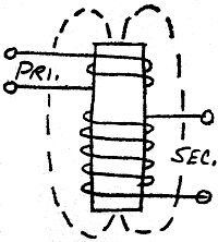  So far, we have described a transformer as two
coils of wire, placed close together along a common axis. Although some transformers
are actually built this way, most use other types of construction. Instead of being
placed side by side, the two coils are usually arranged with one coil inside the
other; this gives much closer and more efficient magnetic coupling. So far, we have described a transformer as two
coils of wire, placed close together along a common axis. Although some transformers
are actually built this way, most use other types of construction. Instead of being
placed side by side, the two coils are usually arranged with one coil inside the
other; this gives much closer and more efficient magnetic coupling.
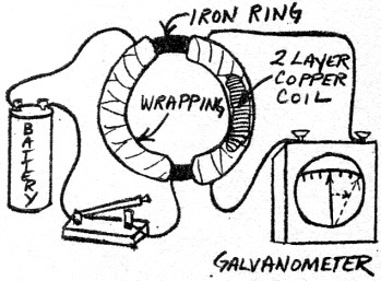
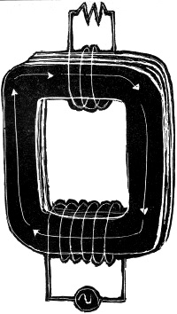
For use at low frequencies, designers wind the two coils around a common iron
core. Since iron is a much more efficient conductor than air, the magnetic field
built up is much stronger. That is, almost all the magnetic lines of force developed
by the primary winding are gathered up by the
 iron core and shaped so that almost all
cut through the secondary winding. Therefore the efficiency of the transformer is
greatly increased. iron core and shaped so that almost all
cut through the secondary winding. Therefore the efficiency of the transformer is
greatly increased.
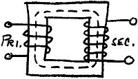
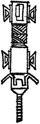
The diagrams at left show the three principal types of iron-core transformers.
First is the open-core transformer which, while possible, is never used because
of its relative inefficiency - a large part of the magnetic field would still have
to be in air, rather than in iron. The closed-core transformer is considerably more
efficient; and the shell core transformer is most efficient of all. The shell-core
type has another advantage: since the flux path is almost entirely contained in
the iron core, it is less subject to disturbances by external magnetic fields than
other types, and it doesn't disturb other nearby circuits as much.
Transformer Losses
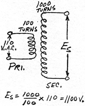
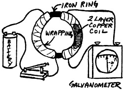 The first transformer ever made was simply
an iron ring with two 2-layer coils of wire wrapped around it. Its inventor was
Michael Faraday, the great English electrical pioneer. He discovered electromagnetic
or mutual induction - the principle upon which the transformer works - in 1831.
When he connected his primitive iron-ring transformer as shown, the galvanometer
needle jumped as the switch was closed. The first transformer ever made was simply
an iron ring with two 2-layer coils of wire wrapped around it. Its inventor was
Michael Faraday, the great English electrical pioneer. He discovered electromagnetic
or mutual induction - the principle upon which the transformer works - in 1831.
When he connected his primitive iron-ring transformer as shown, the galvanometer
needle jumped as the switch was closed.
 Although Faraday's device was a true transformer,
its losses were high. Today's modern, refined transformers have assumed a wide variety
of sizes, shapes, and characteristics as engineers have attempted to minimize the
losses that are a part of every transformer's operation. Although Faraday's device was a true transformer,
its losses were high. Today's modern, refined transformers have assumed a wide variety
of sizes, shapes, and characteristics as engineers have attempted to minimize the
losses that are a part of every transformer's operation.
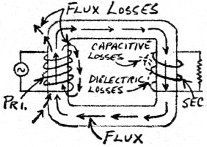
 Transformer losses come from many different
sources. First, not every magnetic flux line cuts the secondary - some simply travel
out into space, consuming energy from the primary, but doing no useful work. This
loss is called flux leakage. Designers minimize it by careful physical arrangement
of the coils and core. Sometimes the primary is wound on the core first, then the
secondary applied on top. At other times the secondary is split into two layers
with the primary in between. Transformer losses come from many different
sources. First, not every magnetic flux line cuts the secondary - some simply travel
out into space, consuming energy from the primary, but doing no useful work. This
loss is called flux leakage. Designers minimize it by careful physical arrangement
of the coils and core. Sometimes the primary is wound on the core first, then the
secondary applied on top. At other times the secondary is split into two layers
with the primary in between.
Copper Losses
The so-called copper losses are caused by the electrical resistance of the transformer
windings. Although copper is a good conductor, it has a measurable resistance, as
does any conductor. When current flows through this resistance, heating takes place
and power is wasted. As a result, almost any transformer will feel warm to the touch
when operating normally, and some are actually hot.
Core Losses
 Since the iron core itself, as well as the
coils, is cut by the expanding and contracting magnetic field, a current is induced
here, too. As this eddy current flows in the core, it steals energy from the primary
circuit and dissipates it as useless heat. The eddy current flows at right angles
to the magnetic flux. It can be reduced by substituting several thin layers of iron
for the solid core. These thin layers - laminations - are separated by layers of
glue which electrically insulate the laminations from each other. In practice, a
small eddy current is set up separately in each lamination, but the total loss is
much less than for a solid-core transformer. Since the iron core itself, as well as the
coils, is cut by the expanding and contracting magnetic field, a current is induced
here, too. As this eddy current flows in the core, it steals energy from the primary
circuit and dissipates it as useless heat. The eddy current flows at right angles
to the magnetic flux. It can be reduced by substituting several thin layers of iron
for the solid core. These thin layers - laminations - are separated by layers of
glue which electrically insulate the laminations from each other. In practice, a
small eddy current is set up separately in each lamination, but the total loss is
much less than for a solid-core transformer.
Still another core loss is caused by the alternating current itself. Since this
current reverses its direction 120 times a second, the iron core - in effect, an
electromagnet - must continually reverse its polarity. And since the minute magnetic
elements in the core tend to resist this change, power must be expended to realign
them. This is called hysteresis loss. Engineers reduce it by building transformer
cores of steels which change magnetic polarity with comparative ease, so that less
power is consumed in making the switch.
Miscellaneous Losses
 Since the turns of wire in a transformer
are close together, there is some distributed capacitance between the turns, between
different layers of windings and between separate windings. This capacitance, though
small, is cumulative. Like a small capacitor connected across the transformer, it
shorts out some of the voltage developed across the windings. At low frequencies
(the usual 60 cps of house current, for example) this loss is unimportant, but at
higher frequencies engineers must go to great lengths to minimize it. Since the turns of wire in a transformer
are close together, there is some distributed capacitance between the turns, between
different layers of windings and between separate windings. This capacitance, though
small, is cumulative. Like a small capacitor connected across the transformer, it
shorts out some of the voltage developed across the windings. At low frequencies
(the usual 60 cps of house current, for example) this loss is unimportant, but at
higher frequencies engineers must go to great lengths to minimize it.
Another small loss is caused by the imperfection of transformer insulation. A
small leakage current will flow through almost any insulator, and thus absorb some
of the transformer's power. This is known as dielectric loss.
Then, too, particularly at high frequencies, a transformer can begin to act as
a small but efficient radio transmitter, and actually radiate power like a broadcast
antenna. This is called transmission loss.
Most of these losses, under normal conditions, are minor, but at times they become
serious. For example, eddy current losses are small at power-line frequencies, but
at the high end of the audio spectrum - say around 20,000 cps - they become significant.
This means that a poorly designed transformer in the output stage of a hi-fi amplifier
will operate much less efficiently at 20,000 cps than at 1000 cps; the result is
poor frequency response.
To minimize eddy currents designers specify thinner laminations. Where laminations
20 to 25 thousandths of an inch thick are used in power transformers designed to
work at 60 cps, audio transformers rarely have laminations thicker than 10 or 15
thousandths of an inch. For really good hi-fi reproduction, lamination thicknesses
may range from ten thousandths of an inch all the way down to only one thousandth
of an inch.
Higher and Higher Frequencies
 As frequencies go still higher, even one
thousandth of an inch is too much, and eddy current losses become excessive. Consequently,
r.f. transformers frequently have cores made of minute grains of iron suspended
in an insulating material and compressed under high pressure into a solid mass.
Since the grains are insulated from each other, they break up the eddy current path
and help reduce eddy current losses. As frequencies go still higher, even one
thousandth of an inch is too much, and eddy current losses become excessive. Consequently,
r.f. transformers frequently have cores made of minute grains of iron suspended
in an insulating material and compressed under high pressure into a solid mass.
Since the grains are insulated from each other, they break up the eddy current path
and help reduce eddy current losses.
As might be expected, the size of the iron granules becomes important as the
frequency increases, since at high frequencies eddy currents are even set up within
the individual granules. Granules several thousandths of an inch thick are satisfactory
below 100,000 cps, but as the frequency goes higher the particles cannot be larger
than several millionths of an inch thick.
A new type of magnetic core made of iron ferrite has recently allowed designers
to build iron-core transformers to operate at frequencies higher than ever before.
These ferrites - varieties of iron oxide, or rust - are valuable because they have
magnetic properties, and yet are insulators and do not conduct current. Because
of the unusual construction of these transformers, no eddy currents form.
If you have bought an ultra-portable radio recently, you are benefiting from
ferrite-improved transformers. Miniature radios of even a few years ago had loop
antennas at least 8 to 10 inches long and almost as high to collect enough signal
to operate. Now ferrite-core antennas, far more efficient because of their magnetic
core but not susceptible to eddy current ills, can be built as small as a short
pencil. As a result, portable radios can now be produced smaller than they have
ever been produced before.
 In many applications, particularly for very
high frequencies, air-core transformers are used. The coils are wound on a non-magnetic
form such as Bakelite or polystyrene. The coils may be concentric, or end to end.
Frequently one is movable, so that the degree of coupling between them is adjustable. In many applications, particularly for very
high frequencies, air-core transformers are used. The coils are wound on a non-magnetic
form such as Bakelite or polystyrene. The coils may be concentric, or end to end.
Frequently one is movable, so that the degree of coupling between them is adjustable.
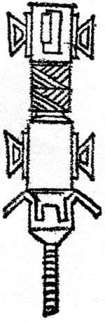
One of the biggest problems in high-frequency transformer design, particularly
where multiple layers of winding are involved, is stray capacitance. If a regular
winding were used, with adjacent layers lying parallel to each other, this capacitance
could become intolerable. Consequently, layers are frequently spiraled back and
forth as in the transformer shown in the drawing at right. This makes adjacent layers
cross each other almost at right angles instead of being parallel, and stray capacitance
is materially lowered as a result.
How the Transformer is Used
The transformer invented in the 1830's wasn't put to work outside the laboratory
until 1885 when William Stanley, an engineer who worked for George Westinghouse,
designed and tested a transformer power-distribution system. He used a 500-volt
generator and fed the power directly into a 4000-foot transmission line. A transformer
to step down the voltage to 100 volts was used at the other end of the line.
Westinghouse wasted no time in putting Stanley's superior transmission system
into operation. That same year he built the first plant especially designed for
transformer power distribution in Buffalo, N. Y. It went into use on November 30,
1886. His generator produced a 1000-volt, 133-cps output which was fed directly
into the transmission line, and stepped down at the customer's home.
In spite of its obvious superiority, however, high-voltage transmission with
transformers did not gain immediate acceptance. Thomas Edison, for one, was violently
opposed to a.c. power, and he used his tremendous prestige to gain support for his
own d.c. system. Consequently, it was not until many years later - after the turn
of the century - that high-voltage a.c. power distribution became common. Even today
there are a few places - some areas of New York City, for example - still receiving
Edison's legacy of d.c. power.
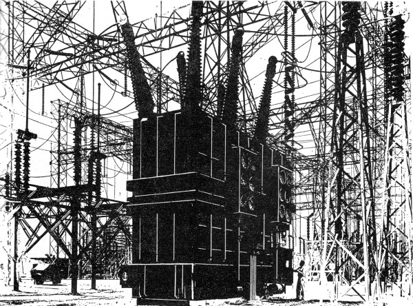
But giant power transformers and their complex distribution stations now dot
the landscape all over the country. The one shown on the next page, one of the largest
ever built, can handle enough electric power for a city of 500,000 inhabitants.
Power Distribution
 Why use transformers for power distribution?
The efficiency of transmission is tremendously increased by stepping up the voltage
to as much as several hundred thousand volts. Also, a given size of wire can carry
far more power at high voltage than low, saving money in transmission costs. Let's
see why. Why use transformers for power distribution?
The efficiency of transmission is tremendously increased by stepping up the voltage
to as much as several hundred thousand volts. Also, a given size of wire can carry
far more power at high voltage than low, saving money in transmission costs. Let's
see why.
As an example, let's take a transmission line of No.1 wire 10 miles long - that's
a conductor about the size of your little finger. The resistance of one such wire
10 miles long is about 7 ohms. (Actually, the resistance of each wire in the transmission
pair is 7 ohms but for the sake of illustration let's consider just one.) Now let's
say that we transmit a current of 120 amperes at 120,000 volts (a common transmission-line
voltage) over the 10 miles. The total power fed into the line at the generating
station is 14,400,000 volt-amperes.
With 120 amperes flowing in the 7-ohm line, the voltage drop over the ten miles
will be 840 volts. Thus, the output voltage will be 119,160 volts; 120 amperes at
119,160 volts gives a 14,299,200 volt-ampere output. Along the line we have lost
100,800 volt-amperes, dissipated by the resistance of the transmission line. This
seems like a lot of power, but if we figure it in terms of percentage, the loss
amounts to a negligible 0.7% of the total fed into the line.
Now let's see what happens if the supply voltage is reduced to only 12,000 volts.
The power input is now 1,440,000 volt-amperes. We will assume that the transmission
line is still carrying 120 amps - its maximum load under any conditions. Since the
current and resistance are the same, the voltage drop over the 10 miles will also
be the same - 840 volts. The loss in the transmission line will still be 100,800
volt-amperes, but now this represents a whopping 7% of the total fed into the transmission
line.
Obviously, the high-voltage transmission is far more efficient. As also demonstrated
in this example, the transmission line can carry far more power under high-voltage
conditions. For these reasons, all transmission lines operate at higher voltages
than those delivered to your electric meter by the power companies.
At Niagara Falls, N. Y., for example, hydroelectric generators produce power
at 6000 volts. It is immediately stepped up by transformers to 120,000 volts and
fed to long-distance transmission lines. At various points it is stepped back down
to 6000 volts for distribution over local areas, then stepped down once again to
230 and 115 volts for home use.
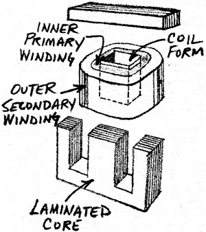
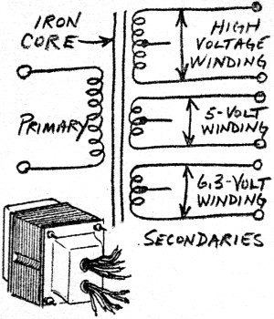
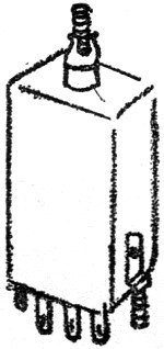
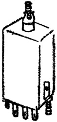
Power Transformers
 Although a power-distribution transformer
is more spectacular, you're much more likely to be familiar with the ordinary power
transformer used in radios, amplifiers, and TV sets. Such devices have a primary
winding and usually several secondary windings to meet the various voltage and current
requirements of a receiver or amplifier; a drawing of a typical power transformer
is shown at right, above. The primary is usually designed for 115 volts; the high-voltage
secondary may produce anywhere from 250 to as high as 600 or 700 volts (higher for
some purposes). The other secondaries, usually rated at 5.0 and 6.3 volts, are for
tube filaments. Although a power-distribution transformer
is more spectacular, you're much more likely to be familiar with the ordinary power
transformer used in radios, amplifiers, and TV sets. Such devices have a primary
winding and usually several secondary windings to meet the various voltage and current
requirements of a receiver or amplifier; a drawing of a typical power transformer
is shown at right, above. The primary is usually designed for 115 volts; the high-voltage
secondary may produce anywhere from 250 to as high as 600 or 700 volts (higher for
some purposes). The other secondaries, usually rated at 5.0 and 6.3 volts, are for
tube filaments.
Power transformers are available with a wide variety of windings and current
capabilities. They may have four, five, six, or even more windings, each rated at
a different voltage for some specific purpose. The high-voltage winding of a light-duty
power transformer may be capable of producing perhaps only 30 or 40 ma., while a
heavy-duty unit may turn out 300, 400, or even 500 ma. Transformers for high-power
transmitters produce voltages and currents far in excess of these values, but for
such applications separate transformers are generally used for high-voltage and
filament supplies.
Audio Transformers
 So far, all the transformers we have talked
about in detail are designed for use in power circuits which operate at 60 cps.
But transformers can operate on a wide variety of frequencies - every audio amplifier
uses at least one transformer of this sort, and many include several such transformers. So far, all the transformers we have talked
about in detail are designed for use in power circuits which operate at 60 cps.
But transformers can operate on a wide variety of frequencies - every audio amplifier
uses at least one transformer of this sort, and many include several such transformers.
Although the same basic principles of step-up and step-down are used in audio
transformers, this is usually of secondary importance to the transformer's ability
to serve as an impedance-matching device. Take, for example, an input transformer.
Here it may be necessary to match a phonograph pickup, a microphone, or other input
source of as little as 200 or 300 ohms (even less, in some cases) to a grid circuit
of as much as several hundred thousand ohms. If the pickup or microphone were connected
directly to the grid, a serious mismatch would occur, which would not only reduce
the efficiency of the circuit but upset frequency response as well. The input transformer
matches the components so that each operates properly.
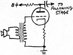
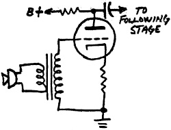
 The interstage transformer is another variety
of the audio transformer and performs much the same kind of job: matching the output
tube-several thousand ohms-to a grid circuit of a much higher impedance. The interstage transformer is another variety
of the audio transformer and performs much the same kind of job: matching the output
tube-several thousand ohms-to a grid circuit of a much higher impedance.
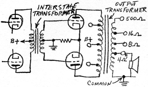
A third variety is the output transformer, whose main task is again impedance-matching.
The plate circuit of the output tubes may have an impedance of many thousands of
ohms, while most loudspeakers are 4, 8, or 16 ohms. To accommodate various tube-speaker
combinations, most output transformers have a series of "taps" on the secondary
winding, and perhaps on the primary as well, so that windings of the proper impedance
can be selected. Only the part of the transformer windings actually used (in 'the
diagram, the portion between the first and second terminals) affects the circuit's
impedance values. One form of output transformer - known as a "universal" type -
is so designed that it is capable of matching virtually any possible tube and speaker
combination.
Better and Better Design
 Great progress has been made recently in
audio-transformer design. Just a few years ago it was difficult to get a transformer
with any appreciable output above, say, 10,000 to 15,000 cps. Today, transformers
with flat outputs up to 20,000 cps are common, while units flat to 50,000 or even
100,000 cps are available. Great progress has been made recently in
audio-transformer design. Just a few years ago it was difficult to get a transformer
with any appreciable output above, say, 10,000 to 15,000 cps. Today, transformers
with flat outputs up to 20,000 cps are common, while units flat to 50,000 or even
100,000 cps are available.
Tremendous problems had to be overcome to produce today's outstanding transformers.
In addition to the losses mentioned earlier, a transformer has inductive reactance
which varies according to frequency (remember that a transformer is also a coil).
At frequencies of 100 and 1000 cps, the inductive reactance of the primary will
be 10 and 100 times, respectively, its value at 10 cps. The inductive reactance
appears to the output tube's plate as a load resistance, and thus various amounts
of amplification take place at various frequencies. As a result, the gain of the
amplifier is about two-and-a-half times higher at 200 cps than at 10 cps. At 3000
cps it would be three times higher. At still higher frequencies, distributed capacitance
becomes an important factor, and gains fall off rapidly.
Engineers go to great lengths to compensate for these effects; by means of special
core materials, unique coil designs, special wrapping patterns, interlaced layers,
and other techniques, they have produced a variety of audio transformers with unbelievably
even response over an extremely wide range of frequencies.
 R.F. Circuits R.F. Circuits
As mentioned earlier, transformers are also widely used in r.f. circuits. Even
the simplest five-tube a.c.-d.c. radio will usually have as many as four transformers,
in addition to its audio output transformer. A typical radio, for example, might
have an antenna coil (actually a small transformer which couples the antenna's output
into the grid of the first amplifying tube), an oscillator coil (a transformer which
supplies feedback for the oscillator), and two i.f. transformers which couple the
various stages.
These transformers are likely to be air, powdered-iron, or ferrite-core transformers,
since a regular iron core would cause intolerable eddy-current losses. The windings
will also probably be of a special spiral design calculated to minimize capacitance
effect,
Special Purpose Transformers
Although the transformers we have been discussing make up the bulk of those used,
there are many other types, all of which perform their useful, specialized jobs.
 The autotransformer, for example, uses only
one winding instead of two, but accomplishes an effect similar to that of a regular
transformer. If the whole coil is used as the primary and only a portion as the
secondary, then it is a step-down unit. Hooked in reverse, it is a step-up device.
This transformer, of course, cannot be used in circuits which must be electrically
isolated from each other. But it serves very well in your automobile where it draws
current from the 6- or 12-volt battery or generator and puts out the 10,000 or more
volts needed to fire your spark plugs. The autotransformer, for example, uses only
one winding instead of two, but accomplishes an effect similar to that of a regular
transformer. If the whole coil is used as the primary and only a portion as the
secondary, then it is a step-down unit. Hooked in reverse, it is a step-up device.
This transformer, of course, cannot be used in circuits which must be electrically
isolated from each other. But it serves very well in your automobile where it draws
current from the 6- or 12-volt battery or generator and puts out the 10,000 or more
volts needed to fire your spark plugs.
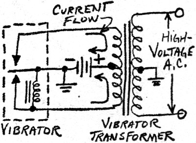
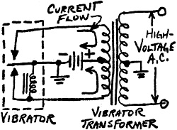
 While we're on the subject of your automobile,
let's take a look at the car radio which uses another kind of specialized device,
the vibrator transformer. This device effectively "transforms" d.c. As the vibrator
element moves back and forth touching each contact in turn, current flows through
each half of the primary alternately, with each pulse going in a different direction.
With the proper turns ratio, the output from the original 6- or 12- volt d.c. source
can be as much as several hundred volts a.c. While we're on the subject of your automobile,
let's take a look at the car radio which uses another kind of specialized device,
the vibrator transformer. This device effectively "transforms" d.c. As the vibrator
element moves back and forth touching each contact in turn, current flows through
each half of the primary alternately, with each pulse going in a different direction.
With the proper turns ratio, the output from the original 6- or 12- volt d.c. source
can be as much as several hundred volts a.c.
Photoflash transformers, used to operate photographer's electronic flash or "strobe"
units, are also vibrator-operated. They can take the vibrator-interrupted output
from a 1 1/2-volt battery and turn it into several thousand volts a.c.
 Pulse transformers are used primarily in
radar. They range from tiny units (several of which can fit in a thimble) that put
out a few millionths of a watt to huge, multi-ton giants that transmit powerful
million-watt pulses. These transformers are designed to step up odd-shaped waveforms
without changing the waveshape. Pulse transformers are used primarily in
radar. They range from tiny units (several of which can fit in a thimble) that put
out a few millionths of a watt to huge, multi-ton giants that transmit powerful
million-watt pulses. These transformers are designed to step up odd-shaped waveforms
without changing the waveshape.
One of the newest types - transistor transformers - are similar to those used
in regular r.f. and a.f. circuits except that their impedances and voltage ratings
are calculated to match the operating requirements of transistors. Some of these
units, by the way, can fit in a cube three-eighths of an inch square, and they weigh
only a fraction of an ounce.
Thus, through the ingenuity of the design engineer, the transformer - though
always operating on the same simple principle discovered by Faraday - can be adapted
to perform hundreds of useful and important services.
Posted March 1, 2022
(updated from original post on 5/14/2014
|