Transistor Topics
|
|
John Bardeen, of Bell Telephone Labs, announced the invention of the transistor 10 years to the month before this article was written in the December 1957 issue Popular Electronics magazine. A decade later, engineers and scientists had revolutionized electronics for commercial, military, and hobby applications. It seems strange to read here about applying transistors at high frequencies, where the definition of "high" is in the hundred of MHz. High power from a transistor was measured in tens of watts. Today they operate into the terahertz realm, and at power in the hundreds of watts. We've come a long way, baby. See other "Transistor Topics" in the series: January 1956, December 1957, March 1958, February 1960, April 1960 Transistor Topics By Lou Garner
In the past few weeks our mail has included a lot of letters asking about high-frequency operation of transistors. There's nothing especially mysterious about transistors at high frequencies. The circuits themselves are quite similar to those used at, say, AM broadcast-band frequencies (550 to 1500 kc.) except, of course, for the values of components in the tuned circuits. But the important thing is to have the proper type of transistor. High-Frequency Operation. Tetrode transistors (see our May 1957 column) may be used up into the hundreds of megacycles. The highest frequency tetrode available at this writing is Texas Instruments' Type 3N25 - this is a p-n-p unit with a cutoff frequency of 250 mc. General Electric, too, offers a whole series of tetrode transistors - the highest frequency unit is the 3N30, an n-p-n transistor with a cutoff frequency of 120 mc. RCA is currently offering the highest frequency triode transistor, the 2N384; this is a p-n-p unit with cutoff frequency of 100 mc. which may be used as an oscillator up to 250 mc. In general, r.f. transistors will serve as amplifiers up to, or slightly past, their nominal "cutoff frequency" (at which their gain is approximately 70% of that achieved at low frequencies), and as oscillators well above cutoff frequency. Take the RCA transistor as an example. With a cutoff frequency of 100 mc., this unit will provide 15 db gain at 50 mc. in a common base amplifier circuit. It provides unity gain at 250 mc. The lowest priced high-frequency transistor as far as the home experimenter is concerned is probably Philco's Type AO-1 surface barrier transistor. With a rated cutoff frequency of 30 mc., the AO-1 is offered at slightly under $2.00 by leading mail order supply houses. All of these transistors are suitable for receivers and low-power transmitters. Unfortunately, no manufacturer is currently offering medium or "hi" power transistors for use at high r.f. values.
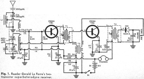
Fig. 1 - Reader Gerald Le Fevre's two-transistor superheterodyne receiver.
Fig. 2 - Two simple uses for a transistorized high-voltage "generator," suggested by reader Charles Rakes: (A) night light; (B) electric fence. Readers' Circuit One- and two-transistor receiver circuits are extremely popular with home builders. Almost all such circuits featured in past columns have used either detector-amplifier or simple regenerative-detector arrangements. These circuits, at best, have limited sensitivity and, usually, just fair selectivity. This month, however, we have a most interesting "maximum performance" two-transistor receiver circuit. Submitted by Gerald Le Fevre, of York Rd., Pavilion, N. Y., as his "favorite," this receiver has a superheterodyne circuit. In addition, it uses a reflex arrangement, permitting one transistor to serve both as an i.f. stage and as the audio amplifier. Coils L1 and L2 are Miller Types 2000 and 2020 respectively. Referring to Fig. 1, you will see that a Sylvania Type 2N94 r.f. transistor serves as a combination mixer-local oscillator. The i.f. output signal developed across the primary of transformer T1 is coupled to the i.f. amplifier stage, a second 2N94. T1 is a Miller 2041. The amplified signal then goes from i.f. transformer T2 (Miller 2042) to a 1N34A diode, which serves as the second detector. The resulting audio signal, appearing across volume control R8, is "reflexed" back to the i.f. stage through audio coupling transformer T3. Finally, the amplified audio output signal is applied across a pair of headphones. (T3 is an Argonne AR-100.) Base bias for the first stage is supplied by voltage divider R1-R2, operating in conjunction with emitter resistor R4, bypassed by C5. Base bias for the second stage is supplied by voltage divider R5-R6 and emitter resistor R7, bypassed by C7. R6 is bypassed by C6; other r.f. bypass capacitors are C4, C8, and C9. Operating power is supplied by a standard 6-volt battery, B1 (such as a Burgess Type Z4). Construction should pose no problem for the experimenter who has assembled other simple transistor receivers. Gerald assembled his unit on a 4" x 4" chassis, but suggests that a small Masonite board will serve as well. A Miller #2112 two-gang unit serves as tuning capacitor (C1a/C1b). All resistors are "1/2 watt units, while all fixed capacitors may be small disc ceramics or paper tubulars. If you assemble one of these receivers, be sure to keep your layout as "clean" as possible, with all signal leads short and direct. Watch the battery polarity... remember that the 2N94 is an n-p-n transistor! Moderate-impedance (2000 to 4000 ohm) magnetic head-phones should be used.You shouldn't need an external antenna for stronger local stations. However, for additional pickup, try connecting an antenna to the "hot" side of the ferrite antenna coil (L1) through a 200-µµfd. ceramic or mica capacitor. To align the unit for best operation, use a standard r.f. signal generator. With a modulated r.f. signal, peak the i.f. transformers for maximum output at 455 kc. Adjust the oscillator trimmer capacitor (across C1b) for tracking at the high-frequency end of the dial (around 1500 kc.) and the padder capacitor (C2) and oscillator "slug" (in L2) for tracking at the low-frequency end of the band (about 600 kc.), "rocking" the tuning capacitor as you do so. If an antenna trimmer capacitor is provided (across C1a), adjust this for maximum output above 1550 kilocycles. High-Voltage "Generator" Reader Charles Rakes, of 4419 Harrison St., Kansas City, Mo., has submitted a pair of interesting applications for a high-voltage "generator" designed around a low-cost power transistor. Referring to Fig. 2, a CBS-Hytron Type 2N256 power transistor is connected as a modified "Hartley- type" oscillator. Base bias is determined by R1. In operation, the a.c. voltage developed across the "primary" winding by the oscillator is stepped up by the secondary and used to operate a small (15-watt) fluorescent lamp (A) as a soft "night light," or power an "electric fence" (B) to keep livestock from straying. Construction of the basic circuit is relatively simple and the wiring is completely non-critical. R1 is a 22-ohm, 2-watt carbon resistor. B1 can be any standard medium or large-sized 6-volt battery (such as a Burgess F4P1 or 2F4). The combination oscillator/step-up transformer (T1) is made from a discarded vacuum-tube audio output transformer. The secondary (low-impedance) winding is partially unwound and center-tapped. It is then rewound and becomes the "primary" winding in the oscillator circuit. The original primary winding (high-impedance) then becomes the high-voltage secondary winding, providing the necessary boost.
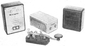
Transistorized code practice oscillators are currently available in kit form from, left to right, Knight (Allied Radio), WRL Electronics and Lafayette Radio. See page 122 for details on all of these units. Code Practice Oscillators Back in April, we reviewed currently available transistorized superhet receiver kits. As a result, we received quite a number of requests that such "reviews" be a regular feature of the column... so here goes with a review of transistorized code practice oscillators. Of the various code practice oscillator (CPO) kits now available, the KT-72, offered by Lafayette Radio (165-08 Liberty Ave., Jamaica 33, N. Y.), is the least expensive. Catalog price is $2.99 (plus postage), including both batteries and a standard hand key. This kit assembles on a small piece of perforated Masonite. The oscillator is designed for headphone operation only. Allied Radio Corporation (100 N. Western Ave., Chicago 80, Ill.), offers a nice CPO which assembles into an attractive black plastic box. It operates from a single penlite cell (included). The kit number is 83Y239 and the catalog price is $3.95 (plus postage), less hand key and 'phones. This unit is also designed for headphone use only. WRL Electronics (Council Bluffs, Iowa) offers a CPO with an easy-to-wire etched-circuit wiring board which assembles in a sturdy aluminum case. Two penlite cells (included) power the circuit. WRL's kit sells for $4.95 (plus postage), and is for headphone operation. The hand key and headphones are available as optional ac-cessories. Lafayette Radio is the only firm currently offering a CPO kit which provides loud-speaker operation. The KT-118 kit assembles into a small plastic case not much larger than a package of cigarettes but which includes the loudspeaker, transistor, battery, and entire circuit. Catalog price of the KT-118, less hand key, is $795 (plus postage). Lafayette Radio's two-transistor "Sunflex" receiver. Sun Batteries While a "sun battery" is not, strictly speaking, a transistor item, it is often used in conjunction with transistorized equipment and, therefore, is of interest to Transistor Topics' readers. The International Rectifier Corporation (1521 East Grand Ave., El Segundo, Calif.) , will shortly release a new silicon solar cell with a lower cost per watt than previously available units. For full specifications, price and availability information, write directly to the manufacturer. Lafayette Radio's latest catalog offers a "Heliodyne" silicon battery at $665 (plus postage). A multicell unit, this solar battery will supply up to 2.0 ma. at 3.2 volts in full sunlight. This is ample power for most small one- and two-transistor radio receivers or amplifiers, and is considerably more than that supplied by standard selenium cells of comparable size and cost. In addition, Lafayette has announced a new two-transistor radio receiver kit, the "Sunflex," designed especially for solar battery operation, It uses a highly efficient reflexed, complementary symmetry circuit which permits two transistors to give the performance of three. Able to operate on standard penlite cells as well as a solar battery, the KT-132 Sunflex receiver kit sells, less earphone and solar battery, for $11.95 (plus postage). That's all for now, fellows. See you next year.
Posted October 27, 2022 |
|

 And a Merry Christmas to you... together
with the sincere wish that your Christmas Stocking will be brimming full with exactly
what you would like old St. Nick to bring-be it a new car, new test equipment, or
a whole cartload of transistors and miniature components.
And a Merry Christmas to you... together
with the sincere wish that your Christmas Stocking will be brimming full with exactly
what you would like old St. Nick to bring-be it a new car, new test equipment, or
a whole cartload of transistors and miniature components.