|
January 1968 Popular Electronics
 Table of Contents Table of Contents
Wax nostalgic about and learn from the history of early electronics. See articles
from
Popular Electronics,
published October 1954 - April 1985. All copyrights are hereby acknowledged.
|
Once upon a time, all
non-passive electronic products and test equipment used vacuum tubes. Since tube
diodes need a voltage bias, even something as simple as a rectifier circuit was
"active." Even though modern day transistorized equipment has largely overcome most
of the disadvantages of solid state versus vacuum tube, in the early days of silicon
and germanium transistors and diodes issues like voltage and power handling and
input impedance was a limiting factor to some applications. Until the advent of
rugged and reliable field-effect transistor (FET) transistors, if you needed a very
high input impedance for an oscilloscope or multimeter, a vacuum tube circuit was
a necessity. A high impedance test instrument input is required with high impedance
device under test (DUT) in order to avoid loading down the DUT with a voltage divider
effect and changing not just the measured voltage level, but also possibly changing
the operation of the DUT circuit. This article from a 1968 issue of Popular
Electronics introduces readers to the relatively new phenomenon of transistorized
multimeters.
The Case for the Transistorized Multimeter - Pro's and Con's of New Type of
Test Equipment

By Leslie Solomon Technical Editor
The ever-increasing use of transistors and IC's in electronic circuitry has produced
new problems for experimenters. Because the voltage levels for proper operation
of solid-state circuits are usually very small - as a look at any solid-state circuit
will show - any change, even slight, in these voltage values can produce improper
circuit operation. The problems start when you try to measure these low-level voltages.
Using a conventional VOM (volt-ohm-milliammeter) is usually a poor way to make
these measurements. Why? Take a close look at the electrical characteristics of
some typical VOM's. In many cases, the input resistance (in ohms-per-volt usually
found on the meter face in one of the corners) on the lowest voltage range is sufficiently
low to cause serious changes in the measured voltage level.
The Bootstrap Circuit
The major reason that a bipolar transistor circuit is a low-impedance circuit
is the fact that the input signal "sees" a parallel combination of the transistor
base bias resistors, the input resistance of the transistor, and the leakage resistance
of the transistor. When the resulting equivalent resistance is calculated, it will
be found to be a low figure.
The input resistance of a transistor is determined by multiplying the emitter
resistor value (if it has one) by the beta (Β) of the transistor. Therefore,
with any reasonable value of resistor, and beta, the input resistance will be high.
This is the reason why emitter-follower circuits are said to be high input resistance
circuits.
With the introduction of improved manufacturing processes, the leakage current
of a good transistor will be very low, thus making the leakage resistance a high
value. The remaining resistance, the parallel combination of the base bias resistors,
unfortunately remains with us, and it is this value that has the greatest effect
on input resistance.

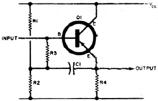
As shown in the schematic of a bootstrap circuit (above), R1 and R2 form the
base bias voltage-divider network, while R3 is an isolating resistor connected between
the base of the transistor and the R1-R2 junction. The signal input is fed to the
base of the transistor and the output is taken across emitter resistor R4 and also
coupled to R3 via capacitor C1.
When a signal appears at the top end of R3 and the base, it also appears at the
emitter in the same phase - and for all practical purposes at the same amplitude.
Thus, an identical signal voltage appears at both ends of R3 and no signal (a.c.)
current flows in this resistor. Resistor R3 then represents an infinitely high resistance
to signal (a.c.) current, thus effectively isolating the base bias resistors. Since
R3 has no effect at d.c., however, the base bias is unchanged. The circuit literally
lifts its impedance by its own "bootstraps," hence its name.
In practice, the signal voltage at the emitter is slightly less than on the base,
thus limiting the effective value of R3. If, for example, the emitter follower voltage
gain is 0.99, and the value of R3 is 100,000 ohms, the effective resistance of R3
is raised to 10 megohms, an increase in value by a factor of 100 times. Dependent
upon the Β (beta) of the transistor in use, and the leakage value of that particular
transistor, the input impedance of the circuit will be a value not too much less
than 10 megohms.
What does this have to do with measuring voltage? If you recall Ohm's law, you
will remember that when two resistors are connected in parallel, the resulting equivalent
resistance is found by (R1 X R2)/(R1 + R2). For example, if you assume that a pair
of 1000-ohm resistors are connected in parallel, the resulting equivalent resistance
is 500 ohms. (We usually remember this equation when we parallel actual resistors
to produce some desired lower value, but we seem to forget it when we connect a
voltmeter into a circuit!)
Now, if you assume that one of the 1000-ohm resistors is a 1000-ohms-per-volt
VOM on the one-volt range, and the other 1000-ohm resistor is in a circuit that
should measure one volt, the resultant 500-ohm equivalent resistance produces a
meter indication of only 0.5 volt - 50% off the circuit value required. In cases
where the 1000-ohm resistor determines current flow in the circuit, reducing its
value to 500 ohms may produce enough current flow to damage a semiconductor. This
is why your VOM probably doesn't give you the voltage level indicated by the manufacturer,
and it is also why some of your semiconductors may have been damaged for unknown
reasons.
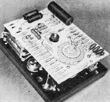
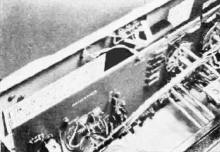
Triplett's Model 600 requires two "AA" cells, one "D" cell, and
one conventional 9-volt transistor radio battery. Note clean appearance of interior.
What about VTVM's? Don't they usually have input impedances measured in megohms,
making them almost non-loading? True, they do have this characteristic - but they
also have several small drawbacks. First, until very recently, most VTVM's had 1.5-volts
full-scale as their lowest range. This meant that the very low voltages (below 0.25
volt) found in many solid-state circuits were indicated at the bottom end of the
meter scale, where, in most cases, they were difficult to read and slight changes
to interpolate were necessary. Second, they required connection to a.c. power, thus
limiting their use to the bench. Third, most VTVM's use vacuum tubes (that's why
they're called VTVM's), and vacuum-tube circuits often require recalibration as
the tubes age.
VOM + VTVM = TVM. Recent VTVM's have overcome some of their disadvantages by
utilizing pre-aged tubes, and incorporating 0.5-volt full-scale ranges. However,
these changes still did not eliminate the need for another voltage measuring instrument
having the total portability of the VOM, the non-loading of the VTVM, full-scale
ranges of 0.5 volt or less, and requiring a minimum of recalibration.
Two developments helped bring such an instrument into being - the FET with its
very high input resistance, and the bipolar transistor "bootstrap" circuit in which
a novel approach makes an ordinary low-impedance transistor circuit look like a
very high impedance circuit. The use of semiconductors meant that batteries could
be employed as the power source, providing portability; and the fact that semiconductor
devices require no "aging" removed the last electronic barrier. The creation of
a low-voltage range is only a component change in the input voltage-divider circuit.
Thus, the stage was set for the introduction of the transistor volt-ohm-milliammeter
or TVM.
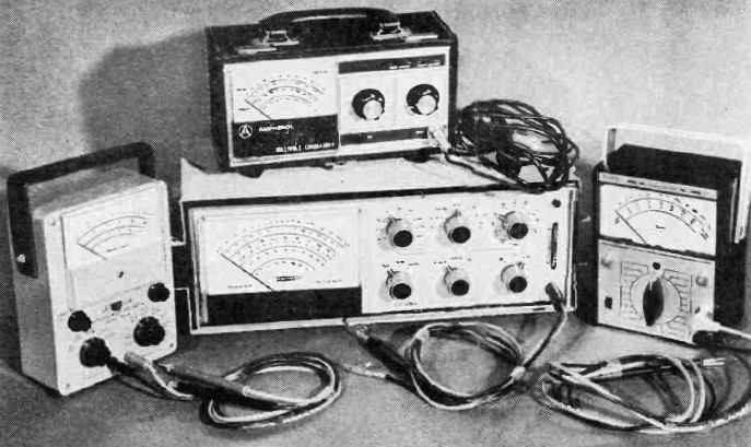
As new TVM's are appearing on the market with regularity, the four units discussed
on these pages represent only a small sampling. However, there are sufficient differences
among them to illustrate some trends in TVM's.
Power Sources
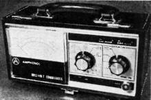

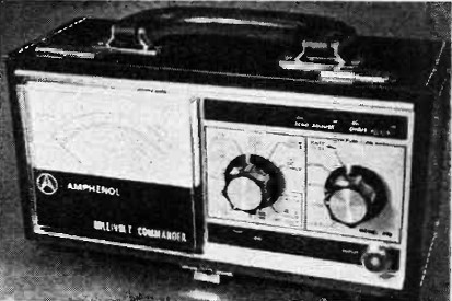
Amphenol's "Millivolt Commander" automatically shuts itself off
when the cover is closed. The detachable cover also contains storage space for the
test leads. Ten "AA" cells are required to power this test set.
As one of the major reasons for the existence of the TVM is portability, most
units are powered only by batteries. There are exceptions - the Heath IM-25, for
example, is powered either by an internal battery supply or by the commercial power
line, with selection made by a front-panel control. When the a.c. power cord is
not in use, it is stored on the rear of the cabinet. TVM's having this feature can
be employed both on the bench and in the field.
Types of batteries used by the various TVM's range from "AA," "C," and "D" cells,
through conventional 9-volt transistor radio batteries. All units have several batteries,
often in various combinations as required by the respective circuit, and, with all,
battery replacement is easy. One unit (the Amphenol "Millivolt Commander ") has
a provision on its function selector switch for testing its internal battery, and
its meter scale is marked accordingly. The others have special, easy-to-perform
test procedures included in their operating manuals to simplify battery testing.
D.C. Voltage Measurements
As TVM's were designed with solid-state circuit voltage measurement in mind,
all are provided with at least a 0.5-volt range, and most also incorporate a 0.15-volt
range. The remainder of the voltage ranges are as found on VTVM's, ranging in 5
to 7 steps to about 1500 volts. Of course, all TVM's have switch provisions for
measuring either positive or negative volts.
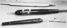
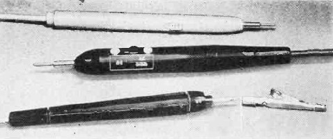
The probe for the Heathkit unit (bottom) has a rotatable end
to select either a.c./ohms or d.c. function, and an optional screw-on alligator
clamp test terminal. Plastic probes used by Amphenol and Triplett (center and top)
both use fingertip-operated function switches.
D.C. full-scale accuracy for all TVM's is between ±2 and 3%. There is
a greater variation in input resistance, however. The Heath and Amphenol units have
about 11 megohms input resistance on all ranges ; the Triplett Model 600 has 2.75
megohms on its 0.4-volt range, 5.5 megohms on its 0.8-volt range, and 11 megohms
on all other ranges ; while the Aul TVM-4 has 500,000 ohms on its 0.15-volt range,
1.5 megohms on the 0.5-volt range, 5 megohms on the 1.5-volt range, 17 megohms on
the 5-volt range, and 36 megohms on all other ranges.
TVM Grand-Daddy?
In August, 1963, Popular Electronics reported on the first commercial
transistor voltmeter - the De Vry TRVM. Still available, it comes as a kit ($64.50),
or wired unit ($89.50), and features a.c. ranges from 5 to 1000 volts, d.c. ranges
from 1 to 1000 volts, and current measurements from 50 μA to 50 mA. External
shunts permit current measurement from 500 mA to 5 amperes, and a conventional ohmmeter
range is provided. Input impedance on a.c. is 650,000 ohms on the 5-volt range and
approximately 2 megohms on the others. The d.c. input resistance is 10 megohms on
all scales except the 1-volt range, where it is about 1 megohm. The device operates
from three "D" cells and one "C" cell.
A.C. Voltage Measurements
As it is seldom necessary to measure low-level a.c. voltages, many TVM's do not
make provisions for such measurement below the usual 1.5 volts. However, there are
exceptions - the Heath unit measures down to 0.15 volt, while the Amphenol unit
goes down to 0.1 volt.
A.C. full-scale accuracy is not quite as good - ranging from 3 to 5%. Input impedance
once again varies widely, ranging from 10 megohms for the Heath and Amphenol units,
to 750,000 ohms for the Triplett, down to 250,000 ohms for the Aul TVM. The frequency
response of the a.c. measurement circuit also shows wide variation. The Heath unit
is flat from 10 Hz to 100 kHz, the Amphenol from 50 Hz to 50 kHz, and the Triplett
from 15 Hz to 2 MHz. Voltage measurements outside these limits may be in error.
D.C. Current Measurement
This seems to be an area of disagreement. While some manufacturers provide for
d.c. measurement - in the case of Heath from 0.015 to 1.5 A (ampere), and Aul from
0.15 to 1.5 A - others do not include this measurement facility.
Since the TVM is a voltage-sensitive device, the inclusion of a series voltage-dropping
resistor in its current measurement circuit may produce external circuit problems.
For example, the insertion resistance of the Heath unit is 10,000 ohms for the 0.015-A
range. When measuring current in a circuit, the user should be aware of the presence
of this unseen series resistance, as in many cases it may curtail certain circuit
operations.
A.C. Current Measurement
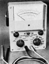
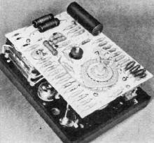
Exterior and interior views of the Aul TVM-4. Although labeled
a transistorized voltmeter, the instrument is actually a transistorized multimeter.
It uses one "C" cell and six "M" cells.
Measurement of low-level a.c. current flow is seldom required in any service
work, and only one unit discussed here (Heath) makes provision for it. In this case,
the a.c. current range duplicates the d.c. range (0.015 to 1.5 A) , and the same
problem of insertion resistance exists as discussed above.
Resistance Measurements
The RCA TVM Entry
As this issue goes to press, we have learned that RCA has introduced the Model
WV-500A solid-state Volt-Ohmyst. Resistance can be measured from 0.2 ohm to 1000
megohms; d.c. voltage measurement is from 0.2 to 1500 volts; and a.c. (r.m.s.) measurement
is from 0.1 to 1500 volts, complex waveforms to 4200 volts. Input resistance on
all d.c. ranges is 11 megohms. Price, $75.00.
As in VOM's and VTVM's, TVM's are provided with the usual ohmmeter ranges. Where
Aul and Triplett are content to go to R X 100K as the upper end of their units,
Heath and Amphenol provide an R x 1M setting.
Three of the representative units have the usual "Zero Adjust" and "Ohms Adjust"
controls; Heath uses a "Zero" control which is common for all functions. Like conventional
ohmmeters, the TVM's use "10" as the center scale indication.
Probe Design
Test leads have also undergone a design evolution during the past few years.
Gone are the days of the unshielded length of wire supplying the "hot" meter input
with a signal. Today, with very high input impedance VTVM's, and now TVM's with
their very low full-scale voltage ranges, stray pickup on the test leads can lead
to erroneous indications. The trend is toward a length of shielded wire terminated
in a plastic probe having some form of fingertip switching between the d.c. and
a.c./ohms functions.
Currently Available TVM's
While all probes are terminated with a reasonably sharp metal tip, many are also
provided with a friction-fit alligator clip that can be slipped over the metal tip.
Heath, on the other hand, uses a threaded metal tip so that the screw-on alligator
clip forms an integral part of the tip.
Physical Design
The modern TVM has that "uncluttered" look. Meters are large, clearly printed,
very easy to read, and range in width up to six inches. Although the familiar box-on-end
packaging is still in vogue for VTVM's and VOM's, TVM's are starting new style trends.

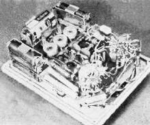
Heath's IM-25 uses 14 "C" cells, two for the ohmmeter function,
and the other 12 for battery operation, installed as shown at left. The IM-25 can
also be operated from a commercial power line if necessary.
Amphenol, for example, encloses its "Millivolt Commander" in a simulated leather
case with carrying handle, with test lead storage space provided in the cover. A
tilting "foot" at the rear of the unit permits standing it at any easy viewing angle.
Another Amphenol novelty is the use of a rocker-type on/off switch so arranged that
when the cover is installed and closed, a rubber bumper on the cover will automatically
switch the unit off if the operator forgets to do so.
Heath is following its latest approach to clean packaging design with retractable
handles mounted on the sides of the unit. The Heath unit, with its multiple functions
and large meter, has gone to a horizontal design, making it the largest of the TVM's
available at present. The IM-25 is the only unit so far that comes either in kit
or factory-wired form.
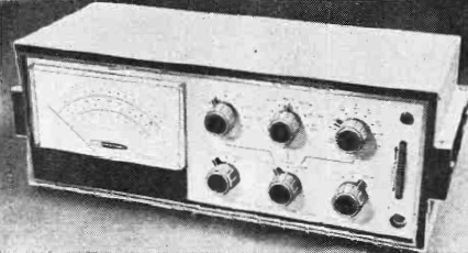
Triplett features a clean, uncluttered front panel with a single large-size function
selector knob and easy-to-read range markings, while the Aul unit is a business-like
service instrument compact enough to fit in a tube caddy.
There also seems to be a wide variation in test lead input jack type. Amphenol
uses a coaxial screw-on fitting, Heath has a telephone type jack, and the other
two representative models use variations of the banana plug fitting.
Conclusions
TVM's are here to stay. At the approximate cost of a VTVM, you now can have a
voltage-measuring device with the very high input impedance of the VTVM and the
portability of the VOM. And, most important, you can now measure down to extremely
low levels of voltage and current with excellent accuracy.
Which one to buy? Obviously, if you do a lot of bench work where line power is
available, the Heath unit comes to the fore. This is also the most versatile of
the TVM's, and can operate from batteries if desired. For greatest all-around portability,
the Amphenol unit, contained within its own carrying case and having an automatic
on/off power switch, will make a hit with most outside servicemen.
The Triplett unit is a very easy-to-use instrument having the simplest operating
controls (only one knob) . It also features a combination handle/foot, for portability
and viewing convenience, and a leather carrying case for protection. The Aul unit
is the most compact of the TVM's covered.
All TVM's are good, and selection should be made based on your needs, present
prices, measurement ranges to be used, and personal taste in instrument appearance
and brand names.
Posted October 14, 2019
|