|
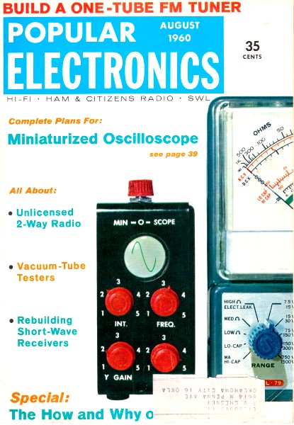
August 1960 Popular Electronics
 Table
of Contents Table
of Contents
Wax nostalgic about and learn from the history of early electronics. See articles
from
Popular Electronics,
published October 1954 - April 1985. All copyrights are hereby acknowledged.
|
 Like a fool, many years ago I donated a perfectly
fine vacuum tube tester that had been given to me by an über-engineer/ham I
worked with during the time (nearly 35 years ago) I was restoring my first vintage
tube radio. Big mistake. It was a really nice tester: a
B&K Model
650 Dyna-Quik Dynamic Mutual Conductance Tube & Transistor Tester. It was
sold shortly after I had also given away as a wedding gift the Crosley floor console
radio that I restored. Another bad move. Now, many moons later, I am working to
restore yet another
Crosley tube radio and I sure wish I had held on to it. Similar
tube testers are routinely selling on eBay for $100-$200. I finally found a really
nice B&K Model 650 on eBay and got it for a decent price. Mistake corrected. Like a fool, many years ago I donated a perfectly
fine vacuum tube tester that had been given to me by an über-engineer/ham I
worked with during the time (nearly 35 years ago) I was restoring my first vintage
tube radio. Big mistake. It was a really nice tester: a
B&K Model
650 Dyna-Quik Dynamic Mutual Conductance Tube & Transistor Tester. It was
sold shortly after I had also given away as a wedding gift the Crosley floor console
radio that I restored. Another bad move. Now, many moons later, I am working to
restore yet another
Crosley tube radio and I sure wish I had held on to it. Similar
tube testers are routinely selling on eBay for $100-$200. I finally found a really
nice B&K Model 650 on eBay and got it for a decent price. Mistake corrected.
Here's the inside story on the devices designed to gauge the vacuum
tube's basic health
Part 1 - Checking for Shorts and for Noise
By G. H. Harrison
The vacuum tube - delicate heart of most electronic equipment - is understandably
subject to many ills. Its elements can become shorted together, disconnected from
their pins, or loose on their mountings. Its filament or heater can burn out, just
like a light bulb. Its cathode, intended to supply a steady stream of electrons
to be shaped and molded by the tube's other elements, can partially "dry up" and
refuse to part with enough electrons. Or its grid or some other element can begin
acting like a cathode and start spurting out an electron stream of its own.
Then, too, the tube itself can become gassy or noisy. Or it can just get "tired
out" - no specific trouble may show up, but the tube simply doesn't have the "oomph"
to do its job properly any longer.

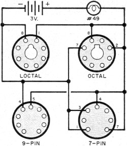
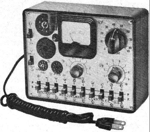
Fig. 1 - A continuity checker, such as the EICO Model 612,
is among the simplest types of tube testers. Helpful in tracking down tube troubles,
it has a pilot lamp which will light if tube filaments or heaters are okay.
Some of these troubles can be tracked down without a tube tester. A simple filament
continuity tester, such as the EICO Model 612 shown in Fig. 1, will quickly
reveal open filaments. Alternatively, an open filament or inter-element short circuit
can be located with an ohmmeter. Tubes suspected of other troubles can be yanked
out and replaced with new ones to see if this makes any difference - if, that is,
you happen to have a spare of the right type on hand or don't mind buying one.
But these methods have their shortcomings. A continuity tester or ohmmeter provides
only the crudest type of test. And the replacement method is subject to error because
other circuit elements, in addition to a defective tube, might be faulty. Thus,
plugging in a new tube in such cases might make no difference, and the troubleshooter
might conclude that the original tube was okay.
For these reasons, service technicians and electronic experimenters look to their
tube testers for quick, accurate information about the condition of- the tubes they
use. Tube testers are equipped to probe every aspect of a tube's "state of health."
Most testers, in addition to giving some general indication of tube quality, also
check for shorts, loose elements, and other possible sources of trouble.
Types of Testers. Tube testers are divided into two general types, depending
on the method used to test overall quality. Some, called emission testers, have
the plate and all grids tied together. A positive voltage is applied to the plate
and grids, and the current in the cathode circuit is measured. In other words, such
testers show just how many electrons the cathode is capable of emitting under given
conditions of plate voltage.
But since the primary purpose of a tube is to amplify (except for diodes and
other special-purpose tubes which are always given simple emission tests), the most
accurate and revealing test is to see how efficiently a tube operates as an amplifier.
This is called mutual-conductance testing. Mutual conductance is simply a measure
of the effect small variations in grid voltage have on plate current. To put it
another way, mutual-conductance testers measure how well amplifier tubes work under
actual operating conditions. Since they are more complex than emission testers,
they naturally cost more.
Let's run through the normal tube-testing procedure to see what you should and
should not do when using a tube tester. We'll digress from time to time in order
to examine some tube-tester circuitry in detail.
Testing for Shorts. First, turn on the instrument and adjust the line-voltage
calibration control. Most testers provide this adjustment-it simply insures consistent
indications by cancelling out normal line-volt-age variations. Next, locate the
tube type to be checked on the tester's tube chart, and set all of the dials and
levers as specified for that particular tube. Make sure that they are all accurately
set, and that you haven't confused two . tubes on the chart with similar designations-a
6J5 for a 6J6, for instance. Now plug in the tube. Wait about 30 seconds for the
tube to warm up, then test for shorts according to directions in the tester's instruction
manual.
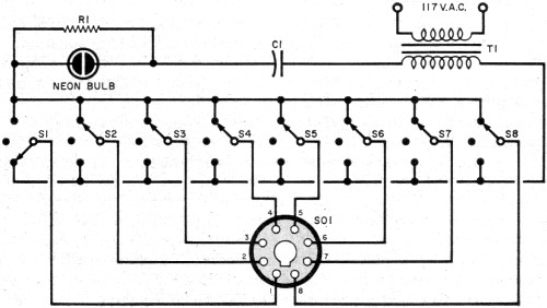
Figure 2 shows how the EMC Model 211 tube-tester checks for shorts. Each element
in the tube under test is connected to the center arm of a s.p.d.t. switch as shown
in this simplified diagram. Next, each switch is thrown to the test position, one
at a time, then returned to "normal." When one switch is in the test position and
the others "normal," all elements except the one being tested are hooked to one
side of a circuit containing a power source and a neon bulb. The isolated element
is hooked to the other side of the same circuit. If a short exists between the isolated
element and any other tube element, the circuit is completed and the bulb flashes
on.


Fig. 2 - Inter-element shorts can be quickly and easily
located with tube testers such as the EMC Model 211. For simplicity, this diagram
of a portion of the 211 's circuitry shows only one of the unit's tube sockets.
In testing for shorts with the EMC 211, as with most other testers, disregard
momentary flashes of the neon bulb when you throw one of the switches. These flashes
are caused by the discharge of inter-electrode and stray circuit capacitances. It's
also a good idea to tap the tube under test gently with your finger throughout the
test; this will reveal any loose elements which might short out under vibration.
While testing for shorts, make sure that the indicator bulb does not glow even
faintly, except for flashes when you throw the switches. A very weak glow, if .continuous,
can indicate a high-resistance leakage path, even though no direct short exists.
Most tube testers are not equipped to make sensitive leakage tests - such tests
were not usually necessary until FM and TV came along. Some AM radios and amplifiers
operate unimpaired with a leaky tube, but sensitive FM and TV circuits generally
react adversely to even the slightest leakage. For this reason, many manufacturers
are now turning out highly sensitive leakage testers, both as separate units and
as part of regular testers. More about this next month.
Incidentally, "shorts" will show up across the filament or heater terminals,
and in cases where single elements are connected internally to more than one pin.
A "short" indication here, of course, is perfectly normal, and the tube-tester chart
will indicate where these normal "shorts" should appear.
If shorts other than normal ones show up during testing, the tube should be discarded.
A shorted tube can, under certain conditions, damage a tube tester if the tube is
tested for emission or mutual conductance. For this reason, tubes should always
be tested for shorts first, and thrown out immediately if shorted.
Testing for Noise
Many testers provide a circuit for testing noisy or potentially noisy tubes,
and this is a logical test to make next. Loose tube elements frequently cause noise.
These elements tend to vibrate, changing inter-electrode spacing and hence capacitance
and other circuit constants.
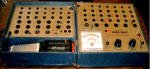
Figure 3(A) shows a simplified diagram of the noise-testing circuit of the Superior
Model TW-11 tube tester. Using a switching circuit similar to that used for short
testing, one element at a time is hooked through a pair of magnetic headphones (crystal
phones won't do here) to one side of a transformer. The other tube elements - all
shorted together - are hooked to the other side. Figure 3 (B) shows a still further
simplified diagram with the grid under test, and the switching circuits eliminated
for clarity. Tap the tube lightly with your finger during the test; if there are
any loose elements, they will vibrate and cause a ringing or "pinging" in the headphones.

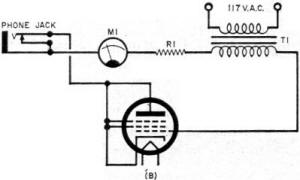
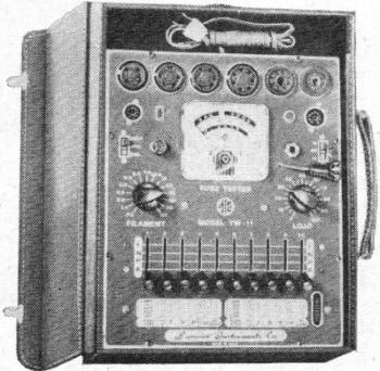
Fig. 3 - Simplified schematic (A) of noise-testing circuit
in Superior Model TW-11 tube tester (see photo to the left). Further simplification
of this circuit (B) shows the tube under test for grid noise; the remaining elements
are connected in parallel.
At this point, we are ready to test emission or mutual conductance - depending
on your tester- and run checks for open elements and gas. Next month, we'll examine
these functions in detail, and look over the field of "quick" testers, cathode-ray
testers, transistor testers, and other special-purpose instruments.
Posted October 6, 2021
(updated from original post on 11/26/2013)
|