|
February 1956 Popular Electronics
 [Table of Contents [Table of Contents
Wax nostalgic about and learn from the history of early electronics. See articles
from
Popular Electronics,
published October 1954 - April 1985. All copyrights are hereby acknowledged.
|
Fortunately, there is
a constant flow of people newly interested in electronics who are seeking information
on basic principles. Some will find an article like this one on Ohm's law fundamentals
and decide maybe being just a user of electronics is good enough. Others will, as
did you and I, read this kind of material and be amazed at how ultimately predictable
electrical circuit parameters are. If he or she continues and launches into a career
in electronics or electrical engineering, it won't be long before he or she will,
as do you and I now, look back at how simple things were at the beginning of the
journey ;-) This 1956 Popular Electronics magazine article was written
half a century ago, but to a word everything contained herein is as valid today
as it was then.
How to Use Ohm's Law
By E.G. Lewis
 Familiarity with this valuable tool will improve
your ability to understand electronic circuits Familiarity with this valuable tool will improve
your ability to understand electronic circuits
Most electronic experimenters steer clear of anything that smacks of theory.
And with good reason, for if one gets a kick out of working with his hands and building
gadgets that do things, pushing a pencil can be mighty boring. But there's one bit
of theory that's both easy to learn and easy to use. Best of ail, once learned,
it will provide the experimenter with a powerful mental tool that will help him
to undertake more difficult and more interesting projects, and may even help him
to save money when buying electronic parts ... Ohm's law.
With a knowledge of Ohm's law, the experimenter can do such things as determine
what size cathode resistor to employ in an audio amplifier, how large a dropping
resistor to install in series vacuum-tube heater strings, and what size multiplier
resistor to use when converting a milliammeter to a voltmeter. In many cases, he
may be able to combine two resistors that he has in his junk box to use in place
of one resistor that he would have to buy, thus saving money on parts purchases.
Ohm's law is not a man-made law like the laws against speeding and robbery but,
rather, a statement of natural or scientific law. It is a statement of the relationship
between electrical pressure (voltage), resistance to current flow (ohms), and actual
current flow (amperes) in a closed electrical circuit. It is named after George
Simon Ohm who, in the 1820's, formulated this relationship. The familiar unit of
electrical resistance, the ohm, is named after the same scientist.
Ohm's law itself may be expressed in many forms, both as fact statements, and
as mathematical formulas. One fact statement is as follows: the current flow (amperage)
in an electrical circuit is directly proportional to the total electromotive force
(electrical pressure, or voltage) in the circuit and inversely proportional to the
total resistance of the circuit.
In actual practice, this fact statement of Ohm's law, as interesting as it may
be, is not used nearly as much as the mathematical relationships, or formulas, which
are derived from the law. These formulas are given in Fig. 1 (A) in their three
basic forms. The small design at the top provides a convenient way for the beginner
to remember the relationships. In using these formulas, the numerical values in
the basic units of resistance (ohms), voltage (volts), and current (amperes) in
every case are substituted for the symbols R, E, and I.
Form one states that:
E = IR
or, voltage (volts) = current (amperes) multiplied by resistance (ohms).
Form two states that:
I = E/R
or, current (amperes) = voltage (volts) divided by resistance (ohms).
And, finally, form three states that:
R = E/I
or, resistance (ohms) = voltage (volts) divided by current (amperes).
Determining Values

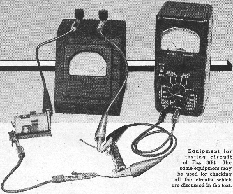
Equipment for testing the circuit of Fig. 3(B). The same
equipment may be used for checking all the circuits which are discussed in the text.
To use any of these forms of Ohm's law, it is only necessary to determine two
of the values in the circuit, then to substitute them in the proper formula to calculate
the third value.
For example, in the basic experimental setup shown in Fig. 1 (B), the electromotive
force or voltage E may be determined by a voltmeter, current flow I by an ammeter,
and the resistance R may then be calculated by using the third form of Ohm's law,
as shown in Fig. 1 (A). But enough of general theory; let's take up some down-to-earth
practical examples.
Series Resistor: In transformerless circuits, tube heaters are frequently connected
in series across a source of fairly high voltage. This may be done if each heater
requires the same current for operation and if the total voltage drop is equal to
the source voltage. Where the total voltage required is less than source voltage,
a series dropping resistor is connected in the circuit to provide additional voltage
drop and thus to limit current flow.
A typical circuit arrangement is shown in Fig. 2 (A). What size resistor
should be chosen for R? Let's use Ohm's law and see.
Using round figures, the total voltage drop 4n the tube circuit proper is 35
volts (35W4) plus 50 volts (50B5) plus 12 volts (12AT7), or a total of 97 volts.
This can be determined by simple addition. Since the source voltage is 117 volts,
it will be necessary to drop 117-97 or 20 volts across the
Resistance. Current? Check the tube manual! For these tubes,
heater current is 0.15 amperes. Now, let's substitute these values in form three
of Ohm's law, as given in Fig. 1 (A). Resistance (R) = desired voltage drop
(20) /current (0.15), or:
R = 20/0.15 = 133.33 ohms
It's as simple as that!
But now a problem presents itself. If an experimenter went into a radio parts
store and asked for a 133.33-ohm resistor, the clerk would be mighty surprised.
In most cases, however, exact circuit values are not too critical, so one should
simply ask for the nearest standard value resistor or, in this case, a 150-ohm unit.
Cathode Resistor: A common problem encountered in designing and building audio
amplifiers is shown in Fig. 2 (B). What size cathode resistor is needed to
bias this power output stage properly? As in the case of the series heater resistor,
first consult the tube manual. Let's assume that a type 50C5 tube is being used,
with B+ around 110 volts.
Referring to the tube manual, it will be seen that suggested bias voltage is
-7.5 volts for this plate voltage, and that, under these conditions, the plate current
will be 49 milliamperes, the screen grid current 4 milliamperes. The cathode current
is the total of the plate and screen currents, or 49 plus 4 = 53 ma.
Having the voltage (7.5 volts) and the current value (53 ma.), the resistance
can be calculated using Ohm's law.
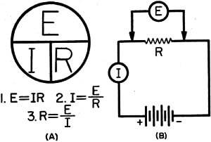
Fig. 1 - (A) Three basic forms of Ohm's law. (B) Experimental
circuit for Ohm's law.
Wait a minute! When using Ohm's law, the current must be in amperes if the values
are to be determined in volts and ohms. Remembering that 1 milliampere equals 0.001
ampere, simply take the value in milliamperes and move the decimal point three places
to the left to convert the value to amperes. Thus, 53 ma. = 0.053 amperes. Now,
substituting this value in the formula:
R = E/I = 7.5/0.053 = 141.5 ohms
As a 141.5-ohm resistor cannot be purchased, one would then ask the clerk for
a 150-ohm unit.
Meter Multiplier: A milliammeter or microammeter may be used as a voltmeter if
it is provided with a series resistor to limit current flow. The basic circuit arrangement
is shown in Fig. 2 (C). What size multiplier resistor should be used in the
circuit? This should be a cinch now that Ohm's law has been learned.
To measure a maximum of 100 volts, a full-scale (1-ma.) reading on the meter
should indicate that 100 volts is applied across the entire circuit. Thus, both
the voltage (100) and the current (1 ma. or 0.001 ampere) are known. Therefore:
Resistance (total) = 100/0.001 = 100,000 ohms
But this is the total resistance needed in the circuit. Since the meter already
has a resistance of 50 ohms, the multiplier resistor (R) should have a value of
99,950 ohms. Where maximum accuracy is desired, a special effort should be made
to obtain a precision multiplier resistor having the exact value needed. However,
for practical purposes, a 100,000-ohm resistor could be used in this circuit.
Series and Parallel Resistors
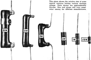
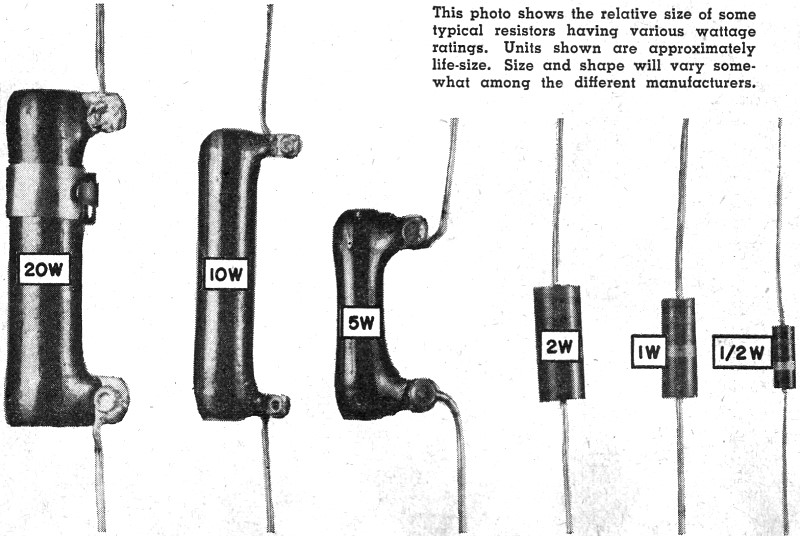
This photo shows the relative size of some typical resistors
having various wattage ratings. Units shown are approximately life-size. Size and
shape will vary somewhat among the different manufacturers.
Suppose that a resistor is needed of a value that cannot be bought ... or, suppose
there are a lot of resistors on hand, but not of the value desired. Is there some
way that two or more resistors can be combined to obtain a special value? There
is.
When resistors are connected in series, the total resistance is simply the sum
of the individual resistance values. A typical series connection is shown in Fig. 3
(A). If the resistors shown had values of 500 ohms (R1), 100 ohms (R2) and 50 ohms
(R3), the total resistance would be the simple sum of these values:
Rt = 650 ohms
When resistors are connected in parallel, the total resistance is less than the
value of the smallest resistor. A parallel resistor circuit, together with the mathematical
formulas used to calculate total resistance, is shown in Fig. 3 (B). Where
only two resistors are in parallel, a special, relatively simple formula may be
employed. This formula is also given in Fig. 3 (B).
As an example, assume that a 300-ohm and 500-ohm resistor are connected in parallel.
Total resistance would then be:
Note that the value obtained (187.5 ohms) is less than that of the smallest resistor
in the parallel network (300 ohms).
Where all the resistors are of the same value, the total parallel resistance
can be determined simply by dividing the value of one resistor by the number of
resistors connected in parallel. For example, suppose there are five (5) one-thousand-ohm
(1000-ohm) resistors connected in parallel. Total resistance would be 1000 divided
by 5 or 200 ohms.
Wattage

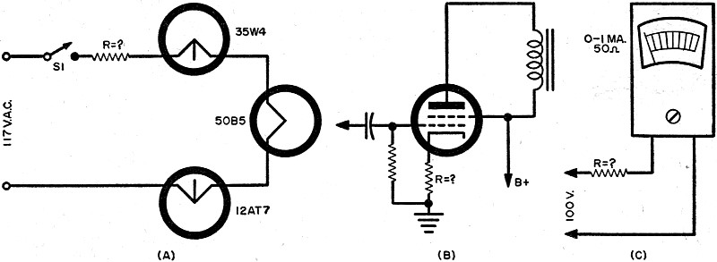
Fig. 2 - Circuits for assisting in determining the value
of the unknown resistor in the following configurations: (A) series healer string.
(B) cathode bias. (C) meter multiplier.
When specifying a resistor size, not only the resistance must be known but also
the wattage rating. All the resistors which are shown on the facing page have exactly
the same resistance value, but there is a big difference in physical size ... and
in price as well.
The wattage rating of a resistor is determined by the amount of current it can
handle, for its resistance, without overheating or burning out. Thus, it is determined
by the power that the resistor can dissipate as heat. Naturally, a large resistor
can dissipate more heat than a smaller resistor, and - as would be expected - the
larger the wattage rating of a resistor, the larger its physical size.
Actual power, in watts, may be determined by the formulas given in Fig. 3
(C). When choosing a resistor for an electronic application, it is common practice
to pick a wattage rating in a standard size at least two to three times the actual
wattage that the resistor must dissipate as heat.
As practical examples, let's determine the wattage ratings of the three resistors
which were chosen for use as a series filament resistor, as a cathode bias resistor,
and as a meter multiplier resistor in the previous examples.
Series Resistor: In the circuit given in Fig. 2(A), it was decided to use
a 150-ohm resistor. To determine the wattage rating, the actual power dissipation
must first be determined, using the first formula given in Fig. 3(C) :
W = I2R = (0.15)2(150) = (0.0225) (150)
= 3.375 watts
Twice this value would be around 7 watts, and the next standard resistor size
is 10 watts. Therefore, in this application, a 150-ohm, 10-watt resistor would be
specified.
Cathode Resistor: In the second example, using the circuit given in Fig. 2(B),
it was determined that a cathode resistor of 150 ohms would be needed to give a
bias voltage of -7.5 volts with a cathode current of 53 ma. Let's round off the
current figure to 50 ma. ... the results will be close enough for practical design
work. Using the last formula given in Fig. 3(C), and changing 50 ma. to 0.050
ampere, the actual power dissipation would be:
W = EI = (7.5) (0.050) = 0.375 watts
In this case, a 1-watt resistor would be used.
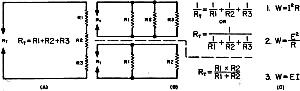
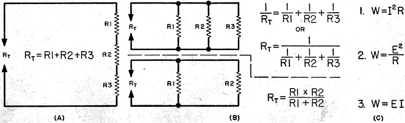
Fig. 3 - (A) series resistors; (B) parallel resistors; (C)
equations for calculating power.
Multiplier Resistor: In the third example discussed, Fig. 2(C), it was calculated
that a 100,000-ohm resistor would be needed as a meter multiplier to change an 0-1
ma. meter to a 0-100 volt voltmeter. Wattage? Let's use the second formula given
in Fig. 3C.
W = E2/R = (100)2/100,000
= 10,000/100,000 = 0.1 watts
And, in this case, a 1/2-watt or even a 1/4-watt resistor would be satisfactory.
Conclusion
In this discussion, the value of learning and using Ohm's law to the average
experimenter has been emphasized. Remember, however, if these problems and examples
seemed a little difficult, that they were so only because of unfamiliarity with
Ohm's law. As practice and experience are gained, calculating resistor values with
Ohm's law becomes easier and easier ... the stage can be reached where most of the
calculations are performed mentally, with pencil and paper seldom being necessary.
But one thing is certain! Learning to use and to apply Ohm's law will result
in a better understanding of circuit action, making it possible to undertake and
to complete successfully a greater number of projects. It will also enable the experimenter
to enjoy his hobby a lot more!
Posted April 7, 2022
(updated from original post on 3/1/2016)
|