|
April 1959 Popular Electronics
 Table
of Contents Table
of Contents
Wax nostalgic about and learn from the history of early electronics. See articles
from
Popular Electronics,
published October 1954 - April 1985. All copyrights are hereby acknowledged.
|
Popular Electronics
magazine ran a 5-part series on test equipment usage. This installment (part 4)
is on the use of a vacuum tube voltmeter (VTVM) for making DC measurements. Don't
pass over the article just because it refers to a vacuum tube tester since there
are lessons that apply to even the most modern transistorized, computerized meter.
Author Larry Klein discusses mainly the DC functions, providing both functional
descriptions of the circuits and how to use them for making accurate measurements.
FET-input digital multimeters (DMMs) have largely replaced VTVMs, but they can still
be found in some older electronics development labs and hobby benches.
Here is
Part 5.
The Vacuum-Tube Voltmeter - D.C. Ranges
 By Larry Klein By Larry Klein
Technical Editor
The last three installments of this series were devoted to the volt-ohm-milliammeter.
Now let's take a look at its chief competition - the vacuum-tube voltmeter (or VTVM).
Why put tubes in a voltmeter? To answer this question, it is necessary to understand
the exact meaning of "sensitivity." As we found when checking out the VOM, the accuracy
of any voltmeter reading depends upon the extent to which it affects the circuit
under measurement. After the voltmeter is connected, the voltage at a particular
point in a circuit frequently no longer has the value it had before the instrument
was attached.
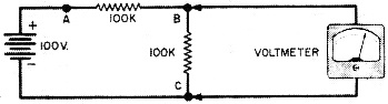
Fig. 1 - Before measurement is taken, the voltage drops
across the two 100,000 ohm resistors are equal. Shunting effect of meter causes
an unequal voltage division and the meter reads less than half the voltage applied
across A and C.
For example, with two equal-value resistors connected across a 100-volt source,
the voltage across each resistor is 50 volts. (See Fig 1). However, a voltmeter
connected across either resistor will read less than 50 volts. Why?
Well, if the VOM in Fig. 1 is a 1000-ohms/volt job, it has an internal resistance
of 100,000 ohms (on the 100-volt range). Therefore, when the meter is connected,
the total resistance between points Band C falls to 50,000 ohms. Since this is only
half as great as the resistance between points A and B, the voltage divides unevenly
and less voltage now appears between points B and C.
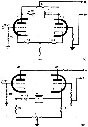
Fig 2 - Alternate versions of the VTVM bridge circuit. Their
basic difference is mainly in the placement of the meter movement.
Of the total 100 volts, 66 2/3 volts will appear from A to B, and 33 1/3 volts
will appear from B to C. The voltmeter therefore reads 33 1/3 volts even though
50 volts was present before the measurement was made.
The higher the internal resistance of a voltmeter, the less current it will drain
from the circuit under test and the more accurate the reading will be. This is the
advantage of the VTVM. Because of its very high input impedance, the VTVM provides
a reading practically identical to the voltage existing before the test leads were
connected.

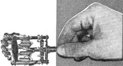
Zero adjust control balances the bridge circuit in the Precise Model 9071 VTVM.
Range switch of the Eico Model 221 with precision divider resistors
wired directly to the switch terminals for rigidity.

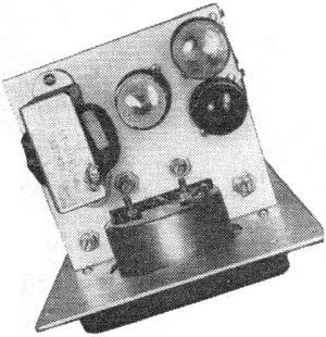
Internal view of the Heathkit V7A VTVM. The range switch is on
the left, function switch on the right.
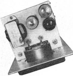
Four calibration controls of the Eico Model 221 are grouped around
the meter movement as seen from the top of the chassis.
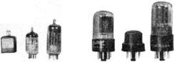
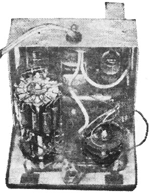
The "active" elements in the VTVM. Standard models usually have
a lineup comprising (from left to right) a 50-ma. power supply selenium rectifier,
a 6AL5 a.c. rectifier and a 12AU7 bridge tube. An alternate arrangement consists
of a 6X5 power rectifier, a 6H6 a.c. rectifier and a 6SN7 bridge tube.
Balanced Bridge. A check of the VTVM circuits shows that most current models
use one or the other of the two bridge amplifiers in Fig. 2. In both circuits
vacuum tube V1 serves as a d.c. bridge whose basic job is to effect an increase
in the sensitivity of meter movement M1. Either circuit can also be considered as
a means of decreasing the input current requirements for deflection of the meter-which
comes down to the same thing. More on this point later.
Tube V1 is usually a 6SN7 or 12AU7 dual triode, and the indicating meter (M1)
is connected from plate to plate or from cathode to cathode of the triodes. In both
circuits, R1 adjusts for the normal differences between the operating currents of
the two triodes and appears on the front panel of the VTVM as the Zero Adjust control.
Calibration control R2 is usually mounted inside the VTVM cabinet and adjusts
for the small changes in total tube current over long periods of use.
If you're wondering why the VTVM circuits is referred to as a "bridge," as you
can see Fig. 2 (B) can be easily redrawn to the standard bridge configuration
(Fig. 3) and may even be more easily understood that way.
The theory of the bridge is quite simple. Triode V1b is the "reference" triode
- in that its grid is grounded and the amount of current flowing through the tube
is determined by the bias developed across cathode resistor R4 and the plate voltage
of about 100 volts d.c. Triode V1a is operating under the same conditions except
that its input grid is connected to a 5- or 6-resistor voltage divider which for
the present discussion we will treat as a single resistor and call R5.
Zero Adjust control R1 varies the plate voltages to tube V1 in Fig. 2 (A)
and varies the cathode bias in the circuit of Fig. 2 (B). By adjustment of
R1, the voltage differences between the two plates or two cathodes can be reduced
to zero - and the meter therefore will also read zero. We have a balanced condition.
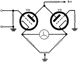
Fig. 3 - The circuit of Fig. 2 (B) redrawn in the standard
bridge configuration.
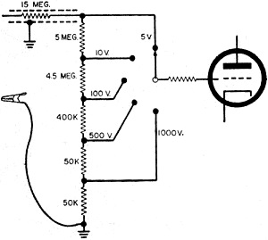
Fig. 4 - Voltage divider which sets the amount of the input
voltage reaching the grid of the input triode.
Unbalancing the Bridge. Now that we have a stable balanced bridge, how do we
go about making practical use of it? Referring back to Fig. 2, let's apply
1 volt d.c. between the input grid of V1a and ground and see what happens. When
the applied positive voltage reduces the bias on V1a, the tube immediately reacts
with an increase in current flow through R3. This, in turn, as Ohm's law tells us,
causes an increased voltage drop across R3. Meter M1, up to this moment, has been
comparing the drops across R3 and R4 and - not finding any difference - read "0."
Now, though, M1 responds to the voltage difference between the plates or cathodes
of V1, swings upscale - and we have a VTVM at work.
Let's take a look at R5. In a practical VTVM, R5 appears as the voltage divider
shown in Fig. 4. The total voltage to be measured is always applied across
the complete string of resistors in the input circuit.
For higher voltage ranges, the input grid of V1 is tapped farther down on the
voltage divider circuit. Note that the input resistance remains constant and equals
the total resistance of the voltage divider plus the isolating resistor in the d.c.
probe. Adding up the resistances in the divider, you can see that the sensitivity
of the VTVM is quite high.
The usual VTVM d.c. input resistance is 11 megohms and can be as high as 25 megohms.
This is most important on the low voltage ranges of the VTVM which are often used
for measurements in high impedance circuits. Note that, unlike the VOM, the input
impedance of the VTVM remains constant regardless of which voltage range is used.
Next month we will continue our investigations and see what makes the VTVM able
to respond to a million cycles a.c. and read up to a billion ohms resistance.
Posted December 28, 2022
(updated from original
post on 12/27/2013)
|