|
May 1960 Popular Electronics
 Table of Contents Table of Contents
Wax nostalgic about and learn from the history of early electronics. See articles
from
Popular Electronics,
published October 1954 - April 1985. All copyrights are hereby acknowledged.
|
While posting this "The
Language of Vectors" article from a 1960 issue of Popular Electronics
magazine, the thought occurred to me whether the terms "vector" and "phasor†" are
interchangeable. I know that a vector is an entity defined, ultimately, by both magnitude and
direction, but then so is a phasor, so are they the same? According to purists, no,
they are not. A phasor is considered a
complex scalar quantity (i.e., phasor =
real ± j imaginary) which can be alternately described as a vector by
translation from rectangular to polar form. The magnitude of a phasor is defined as: magnitude = √(real2
+ imaginary2) and the angle of a phasor is defined as: angle = tan-1 (imaginary/real).
Mathematical manipulation of phasors is done directly according to complex
number rules, whereas manipulation of vectors uses, well, basically the same
types of manipulations after, if necessary, converting them to rectangular
coordinates. Yes, there are dot products and cross products for vectors, but in
the end they are fundamentally the same thing when it comes to mathematics. I'm
sure some will argue the point, but both phasor form and vector forms can be
used interchangeably.
† "Phasor" is a portmanteau of "phase vector."
After Class: The Language of Vectors
 By Saunder Harris By Saunder Harris
Vectors, like shorthand, are used to compress a lot of information into a small
space. Here's an easy-to-follow introduction to the subject
Are you looking for company, Ken?" Larry called up the stair well to his fellow
electronics experimenter.
"Sure am, Larry," Ken replied. "I could use your sparkling company about now.
I've been cracking the books all afternoon."
Larry took the stairs two at a time and reached the attic in a jiffy.
"How's the course coming, old buddy?" he asked as he entered Ken's ham shack.
"With 20-meter DX as hot as it is this afternoon, you must have latched on to something
pretty interesting to keep you off the air."
 "You're modulating 100%, Larry," Ken said
as he looked up from the desk where he had been working. "I'm just finishing my
lessons on phase angles and vectors, and for the first time in ten years of fooling
around with electronics I really understand what phase relations mean. If you can
stand some new knowledge in your thickening skull, I'll be glad to pass it along.
Pull up a chair." "You're modulating 100%, Larry," Ken said
as he looked up from the desk where he had been working. "I'm just finishing my
lessons on phase angles and vectors, and for the first time in ten years of fooling
around with electronics I really understand what phase relations mean. If you can
stand some new knowledge in your thickening skull, I'll be glad to pass it along.
Pull up a chair."
"Okay, professor," agreed Larry, sitting down alongside his friend. "I really
would like to understand more about phase. I know it's important in a.c. circuits
and that sometimes current leads voltage and sometimes it's the other way around,
but that's all. Fire away and teach me something."
"It will be my pleasure," Ken declared, taking up a pencil and paper. "We'll
start right where phase starts - at an a.c. generator." He began sketching as Larry
watched.
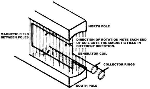
"Follow what I've drawn?" Ken asked.
"Sure thing. The center coil revolves between the two poles. Since each of the
pole pieces is a magnet, one a north and the other a south pole, there is a magnetic
field between them. As the coil revolves, it cuts the field and a voltage is generated
in it. Current flows through the coil and is taken off at the collector rings."
"Good enough, Larry. You do remember your basic electrical theory. Now, let me
ask you ... is this a steady voltage?"
"No, it's not steady because it's an a.c. voltage. I'm not too clear on what
causes an a.c. voltage to vary, though. Here's where the explaining starts, Ken."
"Right. To make the picture clear, I'm going to call in some vectors."
When Larry winced, Ken laughed. "Whatever serious study you do in electronics
will involve a knowledge of vectors, Larry. They're part of the language engineers
use in designing circuits."
Ken took a fresh sheet of paper and started another drawing.
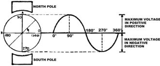
"The circle on the left," he said, "is another view of the generator. The diagram
on the right represents the value of the generated voltage for any coil position.
For example, in the 0° position, the coil is parallel to the magnetic field between
the two poles and no lines of force are being cut. Since a voltage is generated
only when the coil cuts through the magnetic field, the voltage at this point is
zero. That's the way it's shown on the diagram.
"As the coil turns," Ken continued, "it cuts a greater number of lines of force.
The voltage gradually increases until it reaches a maximum value when the coil is
in the 90° position. I've marked this position A, and you can remember it easily
because it makes a right angle with the 0° position.
"From this point on, the angle at which the coil cuts through the magnetic field
decreases and the voltage drops along with this decrease. At the point where the
coil has turned through 180°, which I've marked B, it's back parallel to the magnetic
field and not cutting any lines of force. The voltage here is back to zero. "This
is shown on the diagram by the curved line cutting the base line at the point marked
180°. Do you follow this so far, Larry?"
 "Yes, Ken, but how come the curved line
drops below the base line after the 180° point?" "Yes, Ken, but how come the curved line
drops below the base line after the 180° point?"
"That's a fair question," Ken answered. "Look at the first drawing of the generator
again. You can see that the top of the coil is turning counterclockwise. And now
follow the top of the coil as it turns. At the point where it has turned through
half a circle or 180°, it reverses the direction in which it cuts the magnetic field.
This means that the polarity of the voltage being developed within the coil is also
reversed.
"So, Larry, if the top portion of the curved line in my second drawing is considered
positive voltage, the lower portion would be negative. The point where the coil
top reversed its field is the point marked 180°. Do you get it now?"
"I sure do." The light of new knowledge glinted in Larry's eyes. "I also see
how the term 'alternating current' came into being. It's because each wire in the
generator circuit alternates between plus and minus voltage.
"Let me ask another question, Ken. Is this the same type of voltage that's developed
in an oscillator circuit?"
"Yes it is, Larry. Of course, there's a big difference in the frequencies you
can develop by mechanical means, such as the generator we discussed, and those developed
by electronic means, such as an oscillator tube. In normal house current use, the
generator develops a voltage which goes through 60 cycles a second. (A cycle is
what we call each complete 360° turn of the generator coil.) On the other hand,
an oscillator circuit which has no moving parts can develop voltages up in the millions
of cycles per second."
Ken paused a minute and Larry took the opportunity to ask, "What's so important
about vectors? The way you explained things so far is mighty clear to me."
"As far as we went, Larry, vectors weren't needed," Ken replied. "But when you
get into engineering problems with complicated circuits and a great many voltages
and currents running around, you can't keep track of them with words. You need mathematics
to make the picture understandable, and the part of mathematics used in engineering
work is called vector analysis.
"Even if you never study engineering formally," Ken went on, "understanding a
bit about vectors will make it possible for you to study on your own using engineering
books. What we're doing is learning the ABC's of a new language - vectors."
Smiling, Ken quickly drew two diagrams on the sheet of paper he had been using.
 "Each of these sets of lines," he explained,
"represents the same 360° that the circle did in the last drawing. Leaving out the
circle saves time and work, and, being just as lazy as you and I, the mathematicians
developed this crossed-line system. They call these lines a coordinate axis, but
don't let the big words throw you." "Each of these sets of lines," he explained,
"represents the same 360° that the circle did in the last drawing. Leaving out the
circle saves time and work, and, being just as lazy as you and I, the mathematicians
developed this crossed-line system. They call these lines a coordinate axis, but
don't let the big words throw you."
"Is this co . . . whatever you call it a vector?" Larry asked.
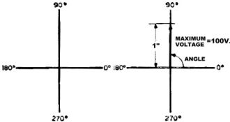
"No, it isn't. Just keep your solder cool, and I'll introduce you to one vector
in half a sec. Let's think of the point where the lines cross - the center point
- as the pivot for the generator coil. When the cycle starts, the coil is lying
right along the 0° line. As it turns through its cycle in the direction of the arrow
in the second set of axes, I can stop it at any point in its swing by drawing a
line out from the center. For example, in this sketch I've stopped the coil in the
position where it's turned through 90°. You can see where I've made the line thicker
at the 90° point.
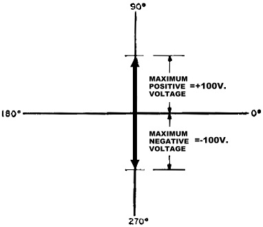
"That thick line is a vector. Remember, Larry, that the voltage was a maximum
when the coil turned through 90°. Well, let's say the maximum voltage generated
is 100 volts. We'll let a length of one inch represent this amount of voltage. So,
if the voltage I want to represent by this vector is the maximum - 100 volts - and
this is generated when the coil is in the 90° position, I make the vector one inch
long and place it along the 90° line."
"You mean, after all that talking, a vector is only a line?" Larry was disgusted.
"Only a line! Why, you... ! Don't let an engineer hear you say that. It's a very
special line and not every line can be a vector. It has certain very special characteristics.
From what we've said, can you tell me what they are?"
Larry thought about it a minute, then replied, "Well, I guess the length of a
vector means something. In this case it measured 100 volts. I'm not sure I get what
other point you're driving at, Ken."
"I don't blame you for not getting it all at once," Ken said. "Vectors aren't
the simplest of subjects at first, but when you understand them you'll find that
they make sense. In the end, you'll use them all the time in following what makes
a circuit tick.
"The two important points about vectors are, first, the length or magnitude of
the vector, and second, its direction, or the way it's pointing. You can say that
every vector has two characteristics : magnitude and direction. These are the important
differences between a vector and an ordinary line."
 Larry was eager to continue. "I think I
have the idea, now, Ken. Why not give me a simple test involving vectors and see
how I make out." Larry was eager to continue. "I think I
have the idea, now, Ken. Why not give me a simple test involving vectors and see
how I make out."
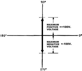
"Fine," said Ken. "Keeping in mind all that we discussed, let's see you add the
vector for the voltage with the coil in a 90° position to the voltage vector for
the coil in the 270° position."
When Larry looked puzzled about getting started, Ken said, "The way you start
any problem in vectors is to draw in the two lines of the coordinate axis and then
to plot the vectors. When you do this, you have a picture of the problem. That's
the reason vectors are such an important tool in simplifying complicated electrical
problems."
Larry went to work following Ken's instructions.
"How's that?" he asked when he had completed the drawing.
"Fine," replied Ken. "But the big question is what the drawing you made means
to you electrically. If you can explain that, you're well on your way to understanding
vector analysis. Start explaining."
"Hmm...," Larry's face frowned with the effort of his concentration. "Well, I'm
not absolutely sure. But looking at the drawing, I would say that the +100 volts
and the -100 volts cancelled each other out. So I guess the result of adding the
two voltages would be zero volts."
He looked up with a relieved expression. "Sure, that's it, zero volts. I guess
it's like a tug of war where one team is as strong as the other - they cancel out
their strength and no one moves."
"You're right, Larry. That's a good way to put it," said Ken. "Adding vectors
is a lot like matching two teams in a tug of war. The result will be the amount
that one team's magnitude in strength, or volts, amperes, ohms, or whatever units
you're measuring exceeds that of the other team."
Larry looked confused again so Ken added, "What happened, did I lose you?"
"You sure did, Ken. Everything was okay with volts, but now you've slipped in
amperes and ohms. You mean vectors can represent other units besides volts?"
 "They certainly can, Larry. Remember that
this all started with a discussion of a generator. Well, at the same time a voltage
was developed, a current was flowing. If you wanted to let the vectors represent
this current, you could have done that just as well. You would let a certain length
of vector - say one inch - represent one amp of current, and you would have current
vectors. You're the one who controls the labels on the vectors. They stand for the
things you want them to stand for. "They certainly can, Larry. Remember that
this all started with a discussion of a generator. Well, at the same time a voltage
was developed, a current was flowing. If you wanted to let the vectors represent
this current, you could have done that just as well. You would let a certain length
of vector - say one inch - represent one amp of current, and you would have current
vectors. You're the one who controls the labels on the vectors. They stand for the
things you want them to stand for.
"Let's take a case where vectors represent currents and show how phase angles
are represented by vectors. Are you clear on the physical meaning of a phase angle,
Larry?"
Larry looked embarrassed. "To tell you the truth, Ken, I've used the term, but
I've never really understood what it meant. This would be a good time to get it
straight. How do phase angles come about, anyway?"
"You're not the only one to be confused by phase angles. It's a confusing subject.
Here's another place where a vector diagram will clear things up for you. Let me
show you what I mean with a drawing of two curves." And Ken made another rapid sketch.
"What I've just drawn," explained Ken, "is a case where two currents - I've called
them current A and current B -are flowing through the same circuit. But they don't
reach their maximum or minimum values at the same time. As you can see from the
curve, when current A starts flowing at the 0° point, current B hasn't begun.
It isn't until current A has reached a maximum value at 90° that B starts to flow.
We say that there is a 90° phase angle between the two currents. '
"This relates back to the generator coil we first drew," Ken continued, "where
the voltages and currents rose and fell according to the number of degrees the coil
had turned. That's where the term 'phase angle' comes into the picture. All it does
is measure the difference between the value of the currents at any one time and
express it in degrees. In this case we would say that current A is We could also
say current A by the statements mean you see.
 "Are you with you again?" "Are you with you again?"
"I'll say this," said Larry. "If you had discussed such a mess before we got
to the vector drawings, I would have been at a loss. Now, I honestly think I can
see what you mean."
"Fine. Let's see you take this curve picture and draw it in vector form." Ken
passed the paper he had been working on to Larry.
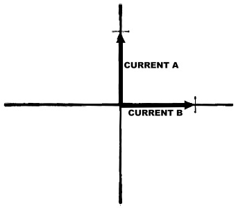
"Okay," agreed Larry. "Let's see, first I draw the coordinate axis, like this.
Then along the 90° axis I'll put in current A to show that it leads by 90°. From
your drawing, Ken, both of the currents are the same strength, which means that
I draw the two vectors the same length."
Larry paused a moment to reflect. "Now, if current B is behind A by 90°, I would
draw it right along the horizontal axis, like so. Here, Ken, how does this drawing
look to you?"
"Nice going, Larry. It looks as though you've got it down pat. I want to add
one point, however. You can also show vectors for current and voltage on the same
diagram. In fact, for a complete circuit analysis, you usually will."
Ken looked at his watch. "Wow, it's getting late and I'm about talked out for
now. How about some milk and apple pie, Larry? We'll save the rest of the vector
discussion for the next session."
"I'm with you on both counts, professor," answered Larry. "Thanks for the info,
and I'll bet I lead you to the eats by 90 degrees!"
Posted August 23, 2022
|