|
November 1942 QST
 Table
of Contents Table
of Contents
Wax nostalgic about and learn from the history of early electronics. See articles
from
QST, published December 1915 - present (visit ARRL
for info). All copyrights hereby acknowledged.
|
Long before there were computer programs
to instantly plot antenna radiation patterns, there were engineers who used slide
rules to generate tables of values for power levels based on fundamental equations,
and then plotted those points by hand on graph paper. Any copies were either hand
generated like the original, or were run off on a mimeograph machine with its characteristic
purple ink. Such was the case for the antenna radiation patterns published in the
November 1942 edition of QST that describes the virtues of a circular antenna in
the UHF band. It is too bad that the author did not include the equations for the
antennas presented; that would really give you an appreciation for computers!
A Circular Antenna for U.H.F.
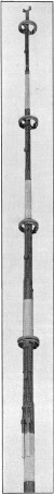
A four-bay circular antenna system model. The bays are fed in
pairs from two main transmission lines.
Technical Review
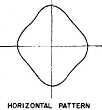
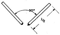
Fig. 1 - The 90·degree V antenna and pattern.
One of the problems that keeps life from getting dull for the radio engineer
is that of designing antenna systems suitable for u.h.f. broadcasting. What is wanted
is a horizontally-polarized system which radiates equally well in all horizontal
directions, has relatively little vertical radiation and at the same time is as
simple as possible both mechanically and electrically.
An interesting type of antenna which fulfills these requirements was described
by M. W. Scheldorf of the General Electric Company in a paper presented at the I.R.E.
Summer Convention. It might be called a "circular end-loaded folded dipole" were
it not for the contradictions inherent in such a description. Designed for f.m.
broadcasting, the antenna gives a substantially circular radiation pattern in the
horizontal plane, is a simple mechanical structure (at least from the commercial
viewpoint), and can be mounted without insulation on a grounded metal pole. The
latter feature is of course highly desirable from the standpoint of lightning protection.
Individual antennas can be stacked to form a multi-unit system giving an increase
in field strength over a single unit. While its resonance characteristic is not
broad enough for good television transmission it is amply broad for wide-band f.m.
The resonant frequency of the antenna is readily adjustable after installation.
The final antenna design was a product of evolution, starting with the cubical
antenna shown in the photograph. This antenna, the first one used for television
broadcasting at the G. E. Helderberg station, consisted of two horizontal sets of
four half-wave elements each, the elements of a set being arranged in the form of
a square. Sub-sequent work showed that the same effect could be secured by replacing
the square set of four elements by a pair of elements arranged in the form of a
V having a 90-degree opening, as shown in Fig. 1. This gave the horizontal
pattern also shown in Fig. 1; the shape could be controlled by altering the
angle between the arms of the V, an angle smaller than 90 degrees giving an improvement
over the pattern shown. However, the antenna was still bulky and the elements had
to be insulated from the support.
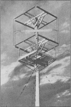
The cubical antenna for television broadcasting. The eight half-wave
elements are arranged in two groups of four, each group forming a horizontal square.
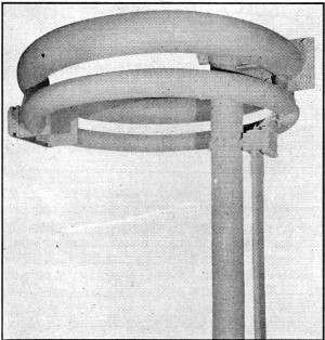
Circular antenna for the f.m. band. It gives a substantially
circular horizontal pattern and does not need to be insulated from the supporting
pole.
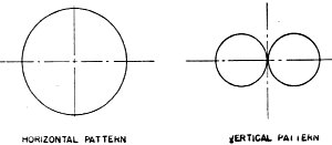
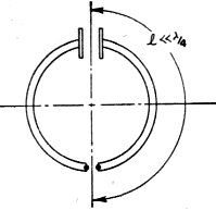
Fig 3 - Simple loop antenna. To obtain a truly circular horizontal
pattern the total length of the loop must be small enough in comparison to a half
wavelength so that the current is substantially the same in all parts.
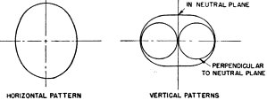
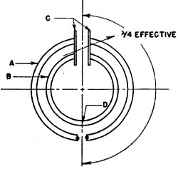
Fig. 4 - The circular antenna described in the text.
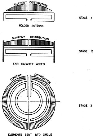
Fig. 5 - Evolution of the circular antenna from a folded
dipole.
The next step is shown in Fig. 2, where the antenna consists of two quarter-wave
sections each bent in the form of a U having sides of equal length, the two sections
being fitted together in the form of a square with two of the sides overlapping.
This gives a cir-cular radiation pattern, since the currents in the overlap-ping
sections are in phase and the resultant" effective" cur-rent tends to be uniform
around the square. This type of antenna also is obviously much smaller than the
V or cubical arrangements. Be-cause of the capacity between the adjacent sections
of the antenna, the overlapping square antenna is practically the equivalent of
a loop an-tenna having capacity loading, as shown in Fig. 3.1
The final system used is shown in Fig. 4. Because the radiation resistance
of a circular antenna such as that shown in Fig. 3 is quite low, a second element
was added to provide a step-up impedance transformation, using the principle of
the folded dipole.2 The effective length of the elements including the
loading of the end capacity C, is one-half wavelength overall.
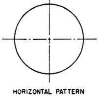
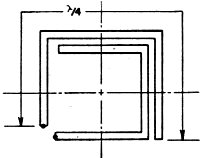
Fig. 2 - Overlapping square antenna.
The actual physical arrangement is shown in the close-up photograph. Point D,
Fig. 4, is at ground potential and the antenna therefore can be mounted directly
on a metal supporting pole at this point, without insulation. In the practical antenna
the elements are made of steel pipe formed into a circle having a diameter of 33
inches, for a center frequency of about 46 Mc. This compares with a length of slightly
over 10 feet for a half-wave dipole at the same frequency.
Fig. 5 shows the development of the antenna from the plain folded arrangement.
In the top drawing, the current distribution is close to that characteristic of
an ordinary half-wave antenna.
By adding end capacity, Stage 2, the current distribution is made more uniform
because an appreciable current flows into the end capacitors. In the final stage
the antenna system is formed into a circle with the end capacitors facing each other
to form a condenser.
The relative diameters of the two elements A and B determine the magnitude of
the impedance step-up. It has been found experimentally that a wide range of impedance
change can be obtained. In the commercial design the terminal impedance is about
35 ohms, at resonance at 46 Mc., when the antenna is mounted on a 4-inch diameter
steel pole. With poles of larger diameter the radiation resistance decreases because
of out-of-phase currents induced in the surface of the pole.
Since the antenna is appreciably smaller than an ordinary dipole, some loss of
signal strength is to be expected as compared to the latter. However, it turns out
that this loss is only one decibel as compared to a vertical dipole (which also
has a uniform horizontal pattern). The antennas can be stacked vertically to increase
the field strength, and it has been found that optimum gain is obtained when the
spacing between units is about one wavelength. The gain in decibels over a vertical
half-wave antenna, as a function of number of antennas or "bays," is shown in Fig. 6.
It can be seen that doubling the number of elements results in approximately 3 db.
gain. This is to be expected in view of the fact that the mutual impedance between
antenna units or bays has been determined experimentally to be very low, when the
spacing is one wavelength, hence the bays act almost independently of one another.
A four-bay antenna for the f.m. broadcasting band is shown in the third photograph.
Each bay is provided with a quarter-wave matching section which matches the antenna
terminal impedance to that of the concentric transmission line used. The matching
sections are lengths of concentric line so constructed that the inner conductor
and the spacing insulators both can be removed after installation. This makes it
possible to vary the size of the inner conductor and also the number of spacing
insulators used when it is desired to bring about an exact match. It has been found
that the surge impedance and velocity of propagation in the line are both inverse
functions of the square root of the average dielectric constant, regardless of the
shape of the insulators used. This relationship makes it possible to predetermine
the performance of the matching section.
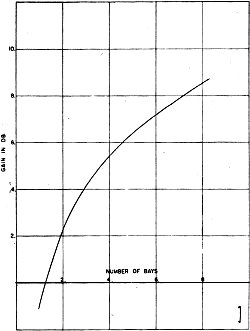
Fig. 6 - Gain of circular an
term a over a vertical half-wave dipole. Bay spacing is 1 wavelength.
1 A. Alford and A. G. Kandoian, "Ultrahigh-Frequency Loop Antennas," AIEE
Transactions Supplement, 1940.
2 P. S. Carter, "Simple Television Antennas," RCA Review, October, 1939.
Posted January 2, 2020
(updated from original post on 8/9/2011)
|