|
January 1953 QST
 Table of Contents Table of Contents
Wax nostalgic about and learn from the history of early electronics. See articles
from
QST, published December 1915 - present (visit ARRL
for info). All copyrights hereby acknowledged.
|
In this 1953 QST magazine
article entitled, "Some ABCs of V.H.F. Receiver Design,"Author Edward Tilton discusses here the
tradeoff between bandwidth and sensitivity in receivers, given that broadband noise
power follows bandwidth in a 10 log BW fashion. Pulling in the most distant stations
requires very low noise in able to get the SNR as high as possible, which requires
the minimum bandwidth possible. Prior to highly stable local oscillators, operating
successfully in a narrow bandwidth for voice (phone), and particularly for CW (Morse
code), dictated the use of a fixed frequency crystal to keep from having to constantly
re-tune the station. Nowadays, of course, what used to be considered a metrology
grade oscillator can be bought for tens of dollars.
Some ABCs of V.H.F. Receiver Design
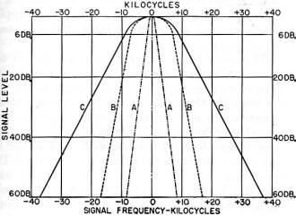
Fig. 1 - Some typical receiver selectivity curves. The narrow
curve, A, is about the best that can be obtained with a 455-kc. i.f. without crystal
filter. It will be superior to the high-fidelity curve, B, in weak-signal v.h.f.
reception. Curve C is representative of the response of receivers having higher
intermediate frequencies.
Hints for Improving Weak-Signal Performance at 50 Mc. and Higher
By Edward P. Tilton,* W1HDQ
The receiver engineers can pass this one up. It is written for the fellow who,
knowing little of the factors that make for good reception, tends to judge a receiver
by its price tag or its appearance. He is more likely to choose a receiver that
harmonizes with his wife's interior decorating scheme, or one that sounds best in
the broadcast band, rather than the receiver that will deliver optimum performance
in the ham bands. And as for building something in the receiving line for himself
- well, he shudders at the thought - if, in fact, he has ever gotten around to thinking
about it.
Now there are many good reasons why we tend, more and more, to let the receiver
manufacturers do the dirty work in designing and construction for us. Unless we
have extensive shop facilities, good test equipment, and considerable experience
in receiver work it is difficult to build a complete receiver for 3.5, 7 or 14 Mc.
that will equal one made by an outfit having these assets. But even if we intend
to work only on the lower bands, we should not fall into the habit of letting the
engineers do all our thinking for us, too! And if we are going to concentrate on
the frequencies from 28 Mc. up, we have little choice but to build our own gear,
if we expect to do a first-class receiving job.
What Makes a "Sensitive" Receiver? We all want to be able to pull in the weak
ones. To be able to hear signals that other fellows miss is a universal amateur
aim, regardless of the frequency we work on. Before we invest a month's pay in a
new communications receiver, or start in building a v.h.f. converter, therefore,
we should know something of the factors that make for superior weak-signal reception.
Up to around 20 Mc. or so there is no very marked difference in the weak-signal
capabilities of the better receivers. Below this region nearly all tubes work well,
and the limiting factor in receiving weak signals is noise generated outside the
receiver. Additional r.f. amplifier stages, no matter how well designed, will serve
mainly to increase such noise in direct proportion to the signals we want to hear.
Thus, adding r.f. gain is similar to tacking on another stage of audio - it will
make the signals louder, but no more readable. In some of the simpler receivers
having no r.f. amplifier stage, or an ineffective one, an external r.f. preamplifier
may be needed to bring up the level of the weakest signals, but in a majority of
cases the only way to hear more DX on 3.5, 7 or 14 Mc. will be to put up a better
antenna, or move to a quieter location.
As we approach the v.h.f. region the picture changes, and our noise level comes
from a different source. Tube performance falls off as we go higher in frequency,
and amplifier stages have to be run "wide open" to produce enough gain to make weak
signals audible. There is still some external noise, to be sure, but much of the
"shush" that is characteristic of a hot v.h.f. receiver is tube noise, generated
within the receiver. At 3.5 Mc., a good receiver with its a.v.c. off and its gain
controls set for optimum weak-signal reception makes little or no noise when its
antenna is disconnected, or the terminals shorted. A good v.h.f. receiver makes
plenty! What, then, are these "low-noise front ends" we talk about in QST and the
Handbook?
The point to remember here is that the noise generated within the receiver, not
that coming in on the antenna, is the limiting factor in v.h.f. receiver sensitivity.
This condition begins to show at 28 Mc. It is much more marked at 50 Mc., and it
is all-important at 144 Mc. and higher. Thus, the more gain an r.f. amplifier stage
provides for a given amount of noise generated, the better will be its weak-signal
performance.
To make the best use of this information, we have to know what makes "tube noise"
and what tubes develop the least for a given amount of gain. Most of this noise
results from electronic action within the tubes, so other things being equal, the
more elements within the tube, the more noise it will make as a v.h.f. amplifier.
Thus, a pentode (with a plate, screen, suppressor and control grid, all contributing
to the total cathode current) will make more noise than a triode, when the upper
limit of its useful frequency range is approached. And these elements add to the
input and output capacitance of the tube, resulting in more capacitive loading of
the tuned circuits to which it is connected.
The principal advantage of the pentode is that, by isolating the grid and plate
circuits it makes possible high gain (over its normal frequency range) without external
neutralizing circuits. When the limit of its operating range is approached it gives
way to the triode, with some circuit tricks added to achieve stability. Well designed
pentode stages work just about as well as triodes at 21 and 8 Mc., but at 50 Mc.
and higher the triodes take over almost exclusively. And even at 21 and 28 Mc.,
the pentodes don't do so well unless the circuits are designed specifically for
these frequencies.
Here, then, is the main reason why the best "all-band" receivers fall down on
28 and 50 Mc., compared to even the simplest converters of the home-built variety.
The first stages of any receiver that covers the broadcast band and the lower ham
bands are designed to give optimum performance there - in the range where they will
be used most. Stability over a wide tuning range, good response to automatic volume
control action (needed to work that popular accessory, the S-meter), and freedom
from cross-modulation troubles dictate the use of tubes that do not perform well
at 28 Mc. and higher. It's a hard fact of receiver design, and no reflection on
the ability of the engineers who develop our commercial receivers, that you can
spend close to a thousand dollars for a receiver and still not get as good performance
on 28 or 50 Mc. as is available with a converter you can build yourself for twenty
dollars or less.
Maybe there will be a really good commercial receiver for the v.h.f. bands someday,
but it has not appeared on the horizon thus far, except in limited-production converter
form.
The Role of Selectivity
Too many v.h.f. men think of selectivity only as an aid to separating stations
on crowded lower frequencies, not realizing that it is also directly related to
the effective signal-to-noise ratio that can be achieved when the receiver is used
with a converter for the v.h.f. bands. All other things being equal, the greater
a receiver's bandwidth the more noise it will make for a given amount of over-all
gain.
Let's look at Fig. 1 for a moment. Here are "selectivity curves" showing
relative receiver response as we tune through a signal. When we understand that
the signal-to-noise ratio of a v.h.f. receiver is inversely proportional to the
area of its selectivity curve, we see at once why we want to use no more bandwidth
than is necessary to pass an intelligible signal.
Curves A and B were taken from the instruction manual of the new Hallicrafters
SX-73. They show the passband of this superb receiver in two of its six selectivity
positions. Curve A is for the sharp i.f. position, without crystal filter.
Curve B shows the broadest response, used mainly for high-fidelity broadcast
reception. From B we see that to drop the signal level 6 db., we have to tune out
7 kc. either side of the center frequency. To drop it 60 db. we must detune 17 kc.
On curve A, we see that the 6-db. points arc only about 3 kc. removed from the center
frequency, and the 60-db. points are only about 8 kc. from the center.
Now we know that to receive voice modulation with good readability, we need only
about 5 or 6 kilocycles bandwidth, and we can get along with even less, if we have
to. Thus, there will be little, if any, difference in the sound of a 2-meter signal
with the selectivity control in either of these two positions, but the receiver
noise that will be present on a weak signal will be vastly greater with the wide
bandwidth.
Consider curve C. This was not taken from any particular receiver, but it is
about the best that could be expected with a receiver having a high intermediate
frequency and no crystal filter. It might be one of those Command sets, with the
2830-kc. i.f. systems, for example. One look at its selectivity curve shows that
this is not going to make a hot v.h.f. receiver, no matter how good a converter
we put ahead of it. The bandwidth would be fine for 2-meter mobile work, but don't
rely on it for home-station use if you want to hear the weak ones.
The bandwidth of the SCR-522 is even broader. That was a fine receiver for non-critical
fixed-frequency work, the purpose for which it was intended. It is not a top-flight
weak-signal receiver, and no amount of work on the front end will make it so. The
way to hop up reception with a 522 or any other broad-tuning receiver, assuming
that you've already done a job on the front end, is to take the output of the high-frequency
i.f. and feed it into a communications receiver, where the passband can be reduced
to the minimum needed for voice intelligibility.
This noise-bandwidth relationship also shows why it is a waste of time to convert
radar-type receivers to amateur use. Progress in our 420-Mc. band has been delayed
several years because of the availability of the APS-13, the BC-645, the BC-788,
the ASB-series receivers and other broadband devices on the surplus market. They're
fine for local work, receiving the broad emissions of modulated oscillators, but
useless for weak-signal DX reception. Just imagine their bandwidth of four megacycles
or more presented in the manner of Fig. 1, and you see why one of these receivers
is a millstone around the neck of the ham who has just jumped into the u.h.f. pool!
One last thought on this selectivity business. So far, we've been talking about
the minimum bandwidth needed for voice. We can't clip much sharper than 3 kc. and
still copy voice modulation. But we can go down to a bandwidth of a few hundred
cycles and get along nicely on c.w. There is an obvious point here for the fellow
who wants to work real v.h.f. DX - there's no way to do it like using high selectivity
and c.w.
Many of the newer crop of double-conversion receivers have selectivity that was
impossible heretofore. With them, and a good v.h.f. converter, we can dig down into
the noise level in a way that we never could before - if we will take advantage
of the possibilities that c.w. operation affords.
You Can't Work 'Em If You Can't Hold 'Em
High selectivity is great stuff - but you don't get that boost in signal-to-noise
ratio for nothing. When you start thinking of bandwidth in cycles, you come up against
stability problems. A wandering oscillator doesn't cause much trouble when the i.f.
bandwidth is 50 kc. or so, but to use selectivity effectively the converter oscillator
has got to stay put!
This rules out tunable oscillators for the average v.h.f. man, so we turn to
crystal-controlled injection sources. A crystal-controlled converter is nice to
have, even on 28 Mc. It is more of a pleasure on 50 Mc. At 144, 220 or 420 Mc. it
becomes a necessity for narrow-band work. Fortunately, crystal control in the converter
is not difficult. Even for 420 Mc., two dual triodes and a low-cost crystal will
provide enough energy in the vicinity of 380 Mc. to replace a one-tube oscillator
covering the same frequency.
And what a difference! - 420-Mc. signals received on a crystal-controlled converter
tune in as easily as a signal on 7 Mc., and c.w. is just as practical. No more holding
one's breath, or tuning signals in and out by waving the hands a foot or two away
from the receiver. It is no exaggeration to say that the general move to crystal-controlled
reception at 144 Mc. and higher in late years has been one of the most potent factors
in demonstrating the utility of these bands for amateur communication.
* V.H.F. Editor, QST.
Posted August 12, 2024
(updated from original post on 9/13/2016)
|