|
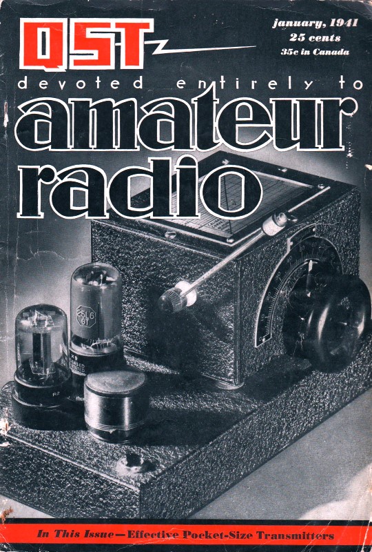
January 1941 QST
 Table of Contents Table of Contents
Wax nostalgic about and learn from the history of early electronics. See articles
from
QST, published December 1915 - present (visit ARRL
for info). All copyrights hereby acknowledged.
|
Wien bridge oscillators had been around for a few years prior
to this article in the January 1941 issue of QST magazine, but evidently
they had not been applied widely to amateur radio applications. In fact, Hewlett-Packard's
very first product, the
Model 200A audio oscillator, employed a Wien bridge oscillator
as its frequency determining circuit. U.S. patent
2268872 provides a detailed description of its operation as well
as the basic schematic. It was considered breakthrough design because its amplitude
and frequency stability rivaled that of the beat frequency oscillators of the day
- at a small fraction of the cost, size, and weight. The Model 200A quickly became
a staple instrument on the benches of designers and launched HP into the Keysight
Technologies it is today (I'll forever wish HP had kept their
name for the Test & Measurement division and called their computers something
else). The Hetrofil first appeared in "Hetrofil -
An Aid to Selectivity" in the September 1939 QST.
An Amateur Application of the Wien Bridge
A. F. Oscillator for General Ham Use
By R. Wade Caywood* W1KRD
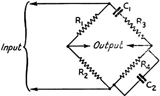
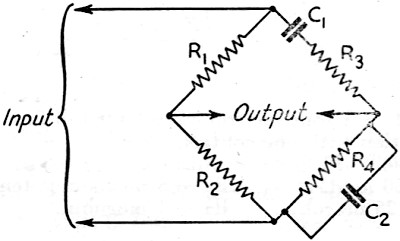
Fig. 1 - The fundamental Wien bridge circuit. Frequencies
for which the bridge is balanced do not appear in the output circuit.
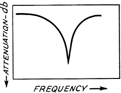
Fig. 2 - A typical selectivity characteristic of the Wien
bridge. This characteristic is basic in audio oscillators using the circuit.
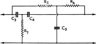
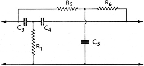
Fig. 3 - The equivalent parallel-T network, for use with
grounded input and output circuits.
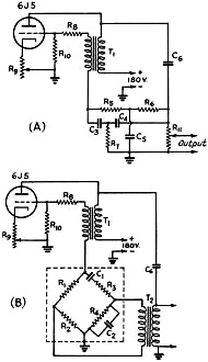
Fig. 4 - Simple bridge audio oscillator circuits. A - using
the parallel-T network; B - using the bridge.
C1, C2 - 0.15μfd.
C3, C4 - 0.15 μfd.
C5 - 0.3 μfd.
C6 - 0.1 μfd. or larger.
R1 - 4000 ohms.
R2 - 2000 ohms.
R3, R4 - 10,000-ohm potentiometers.
R5, R6 - 10,000 ohms.
R7 - 5000 ohms.
R8 - 500 ohms.
R9 - 5000.ohm. variable.
R10 - 0.25 megohm.
R11 - 0.5·megohm potentiometer.
T1 - 3:1 audio transformer.
T2 - 500-2000-ohm transformer.
The above listed values are merely examples. Any resistors and
condensers that satisfy the equations may he used.
The Wien bridge is quite an old timer in the communication game, but it has remained
in the laboratory until recently. During the last year, however, there have been
several commercial applications, although the "Hetrofil"1 is so far the
only amateur device using the principle.
The fundamental circuit, shown in Fig. 1, is quite simple, and with some
modifications can be applied to such uses as heterodyne reduction, oscillator frequency
selection, sound analyzing, frequency measurement, capacity measurement, and condenser
power-factor measurement. Our present concern is with its application in simple
audio oscillator circuits, of the type suitable for speech amplifier testing and
similar uses about the ham shack. Without going into the operation of the bridge,
already covered in Dr. Woodward's article.1 we may say that it is a selective
network with a sharp selectivity characteristic, Fig. 2 being typical.
In many applications of the bridge circuit it is necessary to use a transformer
or a Wagner ground to get balance to ground. The circuit in Fig. 3, the equivalent
parallel-T network,2 has a common ground connection for input and output,
and is therefore frequently more convenient to use. The bridge shown in Fig. 1
can be tuned by varying the two resistors R3 and R4 simultaneously,
or by varying C1 and C2 simultaneously. The equivalent parallel-T
network can be tuned with three ganged resistors, R5, R6 and
R7, or three ganged condensers, C3, C4 and C5.
If, in the circuit of Fig. 1, R1 =2R2, C1
= C2, and the ganged resistors R3 and R4 have the
same value, the simple equation defining the frequency of the null point is:

In the parallel-T network of Fig. 3, if C3 = C4 =
(1/2)C5 and R5 = R6 = 2R7, the equation
is:

Audio oscillators using the Wien bridge or its equivalent parallel-T network
as a selective feed-back network have recently been introduced commercially.3
Essentially such an oscillator is an amplifier with both positive and negative feed-back.
The positive feed-back occurs at all frequencies while the degenerative feed-back
just cancels the positive feed-back at all frequencies except the frequency for
which the network is tuned. By varying this null point, the frequency of oscillation
is varied. An audio oscillator using the Wien bridge or its equivalent-T for the
degenerative feed-back has many advantages over the conventional heterodyne and
LC audio oscillators. The heterodyne oscillator is a complicated affair with many
tubes and circuits; while the LC oscillator requires an iron-core coil and large
condensers to tune to audio frequencies, with the result that the frequency is usually
varied in steps rather than continuously. The Wien bridge oscillator can be made
quite simply, requiring only one tube, and can be tuned continuously by resistances;
in addition, it gives practically harmonic-free output because of the sharp characteristic
curve of the degenerative network.
Fig. 4-A is a simplified oscillator of this type, using the parallel-T network.
The Wien bridge and a transformer are used as the selective network in the oscillator
shown in Fig. 4-B. A Hetrofil can be used as the bridge in the latter circuit.
In both circuits the positive feed-back is obtained through the 1:3 transformer,
T1, with the low-impedance side in the grid circuit. The amount of regeneration
is controlled by the cathode resistor, R9. A by-pass condenser across
R9 is apt to cause the oscillator to produce all sorts of gurgling sounds,
and therefore should not be used. The oscillator can be tuned by either of the methods
previously described. If the feed-back is too great a resistor, R8, of
the order of 500 ohms, will have to be put in series with the grid lead.
The circuit of Fig. 4-A has the advantage of requiring only one cheap transformer,
but has the disadvantage that a three-gang resistor that stays ganged is needed.
Condenser tuning might be used instead, or a number of feed-back circuits could
be switched in or out for different fixed frequencies. The circuit of Fig. 4-B
has the advantage of being easily tuned by a two-gang resistor, but has the disadvantage
of requiring two transformers.
It would be possible to obtain the 180-degree phase shift necessary for degeneration
by using a voltage from the plate circuit of the second section of a double-triode
tube. This would make possible the elimination of a transformer, thereby cutting
cost and reducing size. However, in this connection it must be pointed out that
the two feed-back voltages applied to the grid must be exactly 180 degrees out of
phase. This condition is hard to fulfill when more than one tube is used.
In Fig. 4-A, the resistance of the potentiometer across the output should
be high so that the degenerative voltage is unaffected. The resistors in the degenerative
network should be fairly high in value so that a substantial degenerative voltage
can be developed at low current.
The cathode-resistor control should be advanced only far enough to set up reliable
oscillation. The plate-supply voltage can be varied from about 150 volts to about
450 volts without causing a noticeable shift in oscillator frequency.
At medium and low output, the harmonic distortion is so small as to be negligible.
However, at high output a small second harmonic is discernible. The output volume
is too great for comfort when using a headset, but if greater volume is needed for
loud-speaker operation it would be advisable to add an amplifier rather than to
try to get more output directly from the oscillator. This will keep the harmonic
content to a minimum.
* Engineer, James Millen Mfg. Co., Inc., Malden, Mass.
1 R. W. Woodward - "Hetrofil- An Aid to Selectivity," QST, September, 1939.
2 W. N. Tuttle - "Bridged-T and Parallel-T Null Circuits for Measurements at
Radio Frequencies," Proc. I.R.E., January, 1940.
3 H. H. Scott -"A New Type of Selective Network and Some Applications," Proc.
I.R.E., February, 1938.
Posted November 23, 2021
(updated from original post on 5/8/2016)
|