|
February 1953 QST
 Table
of Contents Table
of Contents
Wax nostalgic about and learn from the history of early electronics. See articles
from
QST, published December 1915 - present (visit ARRL
for info). All copyrights hereby acknowledged.
|
James Kilton
Clapp in 1948 first published details on an oscillator that used positive feedback
obtained from an LC (capacitive & inductive) voltage divider to initiate and
sustain oscillations. Thus was born the now familiar Clapp oscillator. It had an
advantage over both the Colpitts and Hartley oscillators because the feedback, not
being dependent on a simple capacitive or inductive voltage division, respectively,
made it more reliable as a variable frequency oscillator (VFO). This article does
a nice job of explaining the operation of the Clapp oscillator. Just as the Colpitts
and Hartley oscillators handily provide an easy mnemonic for being based on voltage
dividers of capacitance
with the Colpitts
oscillator and inductance (Henries) with the
Hartley
oscillator, the Clapp
oscillator is based on both
capacitance and
inductance (Henries).
The Clapp Oscillator - and How!
An Explanation of the Series-Tuned Colpitts Circuit
By Rex Cassey,* ZL2IQ
In this article, ZL2IQ discusses the principles behind the popular Clapp VFO
circuit, and applies the theory to practice. A discussion of the "remotely-tuned"
Clapp is included.
Many of the peculiar results obtained with the Clapp oscillator can be explained
by a simplified analysis of the circuit, such as the one given below based on the
work of Sandeman of the B.B.C.1 Give it a few minutes' study and you'll
be surprised how many improvements you can make on your oscillator!
|

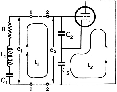
Fig. 1 - Basic Clapp oscillator circuit.
|
The basic r.f, circuit for the Clapp oscillator is shown in Fig. 1. The
oscillatory circuit consists of the series-tuned circuit L1C1
together with its loss resistance R, and the feed-back condensers C2
and C3. The condition where the feed-back energy balances out the losses
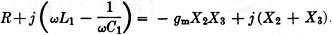
in the circuit, i.e., the condition for oscillations to occur, is given by
R = - gmX2X3
(see Appendix), (1)
where X2 and X3 are the reactances, respectively of C2
and C3.
The condition determining the frequency of oscillation is given by
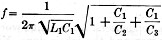 (see Appendix).
Just take another look at that formula (2) above. What does it tell you? Sure
- the frequency of oscillation; but that's not all by a long shot. It also tells
you how to make your oscillator have high stability! Take a good look at that expression
under the square-root sign on the right. It includes C2 and C3,
the feed-back condensers. The value of the effective capacitance of these two condensers
will change as the loading of the oscillator is varied, since they have the effective
grid-cathode and plate-cathode capacitance in parallel with them. However, the resultant
changes in frequency will be quite small because of the effect of that square-root
sign. If we make the tuning capacitance, C1, small and the feed-back
condensers large, the expression under the square-root sign will be very nearly
unity, and the frequency becomes relatively independent of the feed-back condensers
and dependent only on the series-tuned circuit, L1C1. Hence,
dynamic instability attributable to change in tube capacitance is effectively eliminated.
What else can we find out from that expression under the root sign? One thing
is that it can tell us why the oscillator is often called the" series-tuned Colpitts."
It will be seen that the expression never quite reaches unity, but is always slightly
larger. Putting it another way, the oscillator frequency can never be the same as
that of the series-tuned circuit alone, but is always slightly higher. If it were
the same as the resonant frequency of the series circuit, we would have merely a
pure resistance of value R across the e1 terminals of Fig. 1. We
would not expect the circuit to oscillate in that case. However, at a higher frequency
the reactance of the series circuit will be positive and it will look like a small
inductance across the terminals. This is equivalent to the circuit condition we
have in the normal Colpitts! Are the Colpitts and Clapp oscillators the same? No.
Thanks to "Cathode Ray" with his reactance-frequency diagrams," this has been made
abundantly clear. Briefly, if we used only an inductance, the inductive reactance
across the el terminals would vary very slowly with change in frequency. By using
a series circuit, L1C1, however, a small change in frequency
causes a large change in the inductive reactance across the terminals and hence
an extremely small change in frequency will be sufficient to counteract any change
in the phase shift taking place around the feed-back loop. The stability is therefore
very much higher than can be obtained with the normal Colpitts - probably at least
100 times more so.
There is one other difference which may be mentioned as a matter of interest.
In the Colpitts we generally tune by varying the value of the feed-back condensers,
C2 and C3, whereas in the Clapp circuit we vary the "effective"
inductance by altering the series-tuning capacitance. However, the essential difference
does not lie in the method used for tuning, but in the method of providing the effective
inductance in the oscillatory circuit.
Now take a look at that other formula marked (1) above. What can you deduce from
it? Yes, sir, this one's the 64-dollar question. And the answer is that if the value
of the expression on the right-hand side is less than the value of R, the circuit
just doesn't oscillate. If the right-hand side is greater than R, the circuit will
oscillate and the grid current will flow. As grid current increases, the operating
gm falls until the value of the expression on the right-hand side equals
R, when stable oscillations result. There's one thing in particular you should notice
in that formula. You may have the idea that if you increase the Q of the coil, the
efficiency and output of the oscillator will be improved. But take another look
at formula (1). It's not the Q of the coil that's the important factor but the value
of the loss resistance R. If you put in a coil with a higher inductance and a higher
Q, the efficiency won't be improved unless the loss resistance has been lowered
in the process.
Now let's look at some of the problems you can solve by this "oscillation formula."
|
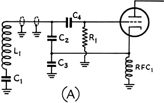
Fig. 2 - Circuits using remote frequency control. In the
circuit of (A), a single coax conductor is used between the tuned circuit and the
feed-back condensers.
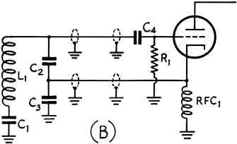
In (B), two cables are used between the feed-back condensers and the tube.
|
Some of the local gang have been telling you that the Clapp oscillator is just
the cat's pajamas for stability, so you decide to build one. You were going to change
from xtal to VFO before the Sweepstakes Contest, anyway. Half an hour before the
contest starts everything is almost ready. You've checked the tuning range of the
series circuit with the grid-dip meter and the range is OK. Fine - you flip the
switch - and what happens? It doesn't oscillate. Wow! Better check the plate voltage
- where did I put that multimeter? Ah, yes, here it is. Just over 300 volts and
the ICAS rating is only 300. Should be getting plenty output. Hmm. Maybe it's a
dud tube. There's a new one in the box at the top of the shelf there. Here she is
- plug it in and let it warm up a bit. Now flip the switch once more - and what
happens? No oscillations. Hmmm. This is going to be a job for the soldering iron.
It's also a job where a look at that "oscillation formula" can be mighty useful.
On the left-hand side of formula (1) we have the loss resistance. We could reduce
it in various ways. For example, we could raise the Q of the existing coil by removing
the shield can and replacing it with a bigger one. This would result in a lower
value of loss resistance, which is what we want. We could prune some turns off the
coil, but this would mean that the series-tuning condenser would be bigger, but
we have already seen that this may reduce the stability slightly. What about the
expression on the right-hand side of the formula? The first part is the gm
of the valve. We've got the correct voltages for the plate (and screen) applied
so we can't very well increase it to make gm bigger. We might be able
to use another value of cathode or grid resistor, though. What else have we that
can be varied? The only other terms in the formula are the reactance of the feed-back
condensers. We could increase the reactance by putting in smaller values of feed-back
condensers, although this would reduce the frequency stability slightly as we have
already seen in connection with formula (2). This would be the easiest way to make
the circuit oscillate; but the best way would be to reduce the loss resistance in
the series-tuned circuit.
You take a look at the clock and find that there's still 10 minutes to go before
the contest starts, so you decide to reduce the values of the feed-back condensers.
A moment's work with the soldering iron and the job is done. You flip the switch
once more, and - bibbety-boppety-boo - it goes!
Nice timing - still 5 minutes to go before the contest starts. You check the
setting for the low-frequency end of the band and then swing the dial to check the
high frequency end and suddenly "plop" - no oscillation. Down again and it's OK.
Up again and it stops. Why? Well, the only term in the oscillation formula which
is dependent on frequency is the reactance of the feed-back condensers. At the higher
frequency the reactance is lower and the gm would have to rise
to counteract the effect. Another quick change is made. With a lower value of feed-back
condenser, everything is OK, and you're off to a flying start in that contest after
all. When it's over, you'll have time to think out ways and means of reducing that
loss resistance in the tuned circuit so that the value of feed-back condensers can
be increased.
One point, which we have not considered so far in our discussions, is the desirability,
or otherwise, of using a grid-blocking condenser such as C4 in Fig. 2.
It is certainly not necessary for the purpose of blocking the high voltage from
the grid of the tube; this is effectively done by the series-tuning capacitance,
C1. Does the inclusion of the grid condenser have any undesirable effect
on the operation of the oscillator? The answer can be found by an extension of our
simplified analysis of the circuit. In the analysis, we assumed that the grid voltage
was equal to i1X2. However, if C4 is included in
the circuit, only a portion of the voltage across C2 will be applied
to the grid, since C4 and the grid-cathode capacitance of the tube now
form a voltage-divider network across the feed-back condenser. If the appropriate
change is made throughout the analysis, it will be found that the right-hand side
of formula (1) is multiplied by a factor of C4/(C4 + Cgc),
while the frequency formula (2) remains unchanged. If the grid condenser is very
much larger than the grid-cathode capacitance of the tube, its effect may be neglected.
However, it must be remembered that under operating conditions, the grid-cathode
capacitance may be as much as 30 or 40 times the static value. In the case of a
triode, it may be as high as 100 μμfd. as a result of the Miller effect, with
a 100-μμfd. condenser for C4, only half the voltage would be applied
to the grid. In this case the circuit would not oscillate so readily and it may
be necessary to reduce the value of the feed-back condensers to offset the effect,
with a resultant loss in stability. In general, we deduce that the grid-blocking
condenser is undesirable in the case of a triode, since it reduces the efficiency
and stability of the oscillator. In the case of a pentode it has little effect but
is still an unnecessary element in the circuit.
Since this dissertation has been prepared as a result of reading a very interesting
article by W3ASW in August QST,3 it may be of interest to comment on
the effects found in the remote-controlled VFO which he described. The appropriate
circuits are shown in Fig. 2.
In a description by W9ERN of a somewhat similar arrangement.4 it has
been pointed out that 70-ohm coaxial cable has a capacitance of about 20 JLJLfd.
per foot. Two lO-foot lengths were, in fact, used by W9ERN in place of C2 and C3•
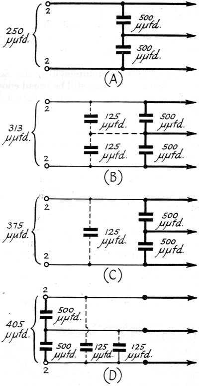
In the circuits shown in Fig. 2, each of the lengths of coaxial cable would
have a capacitance of about 125 μμfd. The effect of this additional capacitance
will depend on how it is introduced into the circuit and a number of cases are shown
in Fig. 3. The circuit in A shows the normal condition, while those in B, C,
and D contain added capacitance. In the normal case A, the effective capacitance
which has been placed across the series-tuned circuit is 250 μμfd. For the
other circuits, this value will be found to have been increased to 313, 375, and
405 μμfd., respectively. In the case of B, the values of X2 and
X3 in our oscillation formula (1) above will have been reduced and the
circuit will not oscillate so readily. The original conditions could be obtained
by simply reducing the 500-μμfd. condensers to 375 μμfd. This is effectively
the arrangement used by W9ERN in his oscillator circuit. However, in order to use
this arrangement, a grounded-cathode oscillator circuit must be adopted. This does
not present any difficulty.
In the case of C, which is equivalent to Fig. 2B, and in the case of D,
which is equivalent to Fig. 2A, it will be noticed that the feed-back condensers
have been by-passed by the 125-μμfd. capacitance of one of the coaxial cables.
This results in a portion of the current i1, which flows in the oscillator
circuit, being ineffective insofar as the production of grid voltage across C2
is concerned, and hence lowers the efficiency of the oscillator. If we increase
the current flowing in the series-tuned circuit to make up for this by-passing effect,
more energy will be lost in the resistance of the series-tuned circuit and this
will tend to offset the improvement we may have made. Looked at from another point
of view, the effect is similar to that of adding capacitance across a crystal holder,
a practice which we know from experience to be undesirable.
|
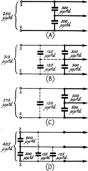
Fig. 3 - The effect of additional cable capacitance across
the feed-back condensers will depend upon where the capacitance is introduced. as
discussed in the text.
|
Mention has been made by W3ASW of the apparently excessive loss in the coaxial
cables when they are inserted between the series-tuned circuit and the feed-back
condensers. This may have been a result of the increased current brought about by
the by-passing effect of the coaxial cables. In his final circuit arrangement, the
majority of the circulating current has been confined to the remote control box
by placing the lumped capacitance of the feed-back condensers in that position,
so that any losses in the coaxial cables should have been reduced.
In closing, here's hoping I'll be seeing you on 7023 kc. some time. Yes, I'm
"rock bound," but not for long (I hope) now that I know where to look for some of
the bugs that are going to arise when I build that new Clapp VFO oscillator!
Appendix
Suppose that an r.f. current, i1, is flowing around the circuit in
the direction shown. The voltage developed across the terminals 1-1, is equal to
i1z1 that is,
Consider now the voltage developed across the feed-back condensers across the
terminals 2-2. Let the plate current be
i2 = gmeg = gm(i1jX2).
The voltage developed across the feed-back condensers will be the sum of the
voltages produced by the two currents which are flowing.
That is, 
If the two voltages we have found above are exactly equal, we have the normal
condition for stable oscillations in the circuit. If we equate the two expressions
we have found for the voltages, and cancel out the term i1, since it
is common to both sides, we get
If we equate the real terms in the above expression, we get
R = - gmX2X3. (1)
Equating the imaginary terms now,
 (2) (2)
*92 Amritsar St., Wellington, N. Z.
1 E. K. Sandeman, Radio Engineering, Vol. I, p. 421,1947.
2 Cathode Ray, "Series or Parallel," Wireless World, August, 1952, p. 321.
3 Long, "Cutting Down VFO Drift," QST, August, 1952, p.20.
4 Clemens, "The R.C.O. - A Remote Control Oscillator," Radio & Television
News, August, 1952, p. 40.
Posted September 20, 2021
(updated from original post on 5/8/2015)
|