|
November 1953 QST
 Table of Contents Table of Contents
Wax nostalgic about and learn from the history of early electronics. See articles
from
QST, published December 1915 - present (visit ARRL
for info). All copyrights hereby acknowledged.
|
"The construction used in the coaxial
antenna at W9YVZ overcomes objections based on appearance - it is no more noticeable
than an ordinary clothesline pole. It even serves as one when necessary!" That line
from a 1953 article in QST magazine demonstrates how long Amateur radio
operators have been battling neighbors for the right to erect an antenna - or antennas
- on private property. Many community associations have codified rules prohibiting
visible antennas of any sort, with the exception of the small satellite TV dishes.
Fortunately for Hams, the U.S. House of Representatives just passed the
Amateur Radio Parity Act, which prevents home owner associations
from a carte blanche banning of antennas. It guarantees the ability to establish
antennas in a minimally intrusive manner. That said, I have seen instances of homes
on small lots with antenna farms - often old and seemingly unattended - that are
eyesores to people who do not have the appreciation for amateur radio that those
of us reading this article have.
A Coaxial Antenna for Ten Meters
A Self-Supporting Vertical Antenna for Restricted Space
By Harry M. Neben,* W9YVZ
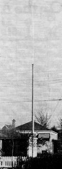
The construction used in the coaxial antenna at W9YVZ overcomes
objections based on appearance - it is no more noticeable than an ordinary clothesline
pole. It even serves as one when necessary!
The vertical antenna, especially when self-supporting, is always attractive when
space is at a premium. Here is a way to build a ten-meter coaxial antenna without
resorting to special fittings. It's especially good for "ground-wave work" and for
contacting mobiles. The ham who has an antenna space problem and yet desires efficient
operation on the ten-meter band may well want to consider a vertical antenna. A
suitable vertical antenna can be made self-supporting, and is non directional. For
fixed-station-to-mobile operation, the vertical antenna gives consistently better
results than a horizontal antenna.
The antenna at W9YVZ is of the coaxial type, and not only works well but is very
inconspicuous. When constructed as described, it is scarcely noticeable in the yard
and thus dispels any objections from the landlord or XYL. In fact, at W9YVZ the
antenna doubles as a support for the Monday wash line.
The Vertical Antenna
The common type of end-fed vertical antenna has a tendency to have serious feed-line
radiation when fed with an open line. The use of coaxial feed may materially reduce
line radiation provided the antenna is properly decoupled from the outside of the
coax. A concentric J antenna for wide frequency band operation or a coaxial antenna
for narrow frequency band operation will provide this decoupling and also will provide
a suitable match to the coaxial cable. The coaxial antenna has enjoyed great popularity
in the past in narrow-band commercial v.h.f. stations where a non directional vertical
radiator is required, and a low radiation angle is desired. The concentric J antenna,
a rather recent development, has proved its superiority where maximum transfer of
energy to the antenna over a wide frequency range is essential. However, for ham
applications, the coaxial antenna performs adequately and is easy to construct in
the home workshop.
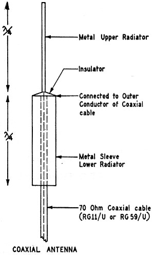
In the coaxial antenna, the center conductor of a 70-ohm coaxial transmission
line or cable is extended one-quarter wavelength beyond the end of the cable and
acts as the upper half of a half-wave antenna. The other half of the antenna is
provided by a quarter-wave sleeve, the upper end being connected to the outer braid
of the coaxial cable, as shown in Fig. 1. The coaxial feed is run through the
sleeve and very little current is induced on the outside of the line by the antenna
field. The feed line of the coaxial cable is practically nonresonant since its characteristic
impedance is quite close to the center impedance of a half-wave antenna.
Antenna Construction
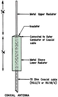
Fig. 1 - Basic construction of the coaxial antenna. Lengths
are electrical, including allowance for length/diameter ratio.
The coaxial antenna consists of an upper metal radiator, a metal sleeve section,
and support mast. The components of this antenna were obtained from a surplus store,
the tinsmith shop, and the local plumbing shop.
The upper radiator is a surplus whip antenna still available in most surplus
stores. However, a mobile whip antenna may be used in place of the surplus antenna
and with its insulator may even simplify the construction. The mounting insulator
for the whip section is a surplus porcelain feed-through insulator with a feed-through
hole which just permits the end of the whip to pass through. The paint was removed
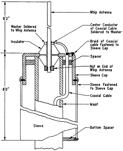
from the end of the whip, a washer soldered to the whip about 3 inches from the
end, and the end of the antenna whip threaded as shown in Fig. 2. This permits
the antenna and insulator to be secured to the sleeve cap much as one would tighten
the feed-through insulator to a panel, and provides a lug for connecting the center
conductor of the coaxial cable to the antenna whip section.
The sleeve section of the antenna consists of an 8-foot length of 3-inch galvanized
iron air duct, and was obtained at the local tin-smith shop. The sleeve section
is 2 inches shorter than the whip section of the antenna in order to compensate
for the difference in diameters of the whip and sleeve sections. Originally, both
the whip and sleeve radiators were made the same length; however, when an effort
was made to reduce the standing-wave ratio on the line, it was found it was necessary
to shorten the sleeve section. This substantially reduced the standing-wave ratio.
The cap of the sleeve is a pipe cap which just slips into the antenna sleeve
and was obtained from the plumber's shop. The hole for the upper radiator feed-through
insulator was cut with an ordinary fly cutter. The pipe caps are usually cast iron
and cutting the hole was fairly easy.
A hole is drilled off center to permit making the connection between the coaxial
cable and the upper whip section and the sleeve section. The galvanized iron sleeve
section is fastened to the pipe-cap skirt by means of self-tapping sheet metal screws.
The mast consists of a 20-foot length of 1-inch galvanized iron pipe. A half-inch
hole is drilled in the pipe about three inches from the top and another 14 feet
from this end; these are for entrance and exit of the coaxial cable. The holes were
slightly elongated by "wobbling" the drill to permit easy passage of the coaxial
cable. However, these holes are not really necessary as the coaxial cable may be
run outside the mast if desired.
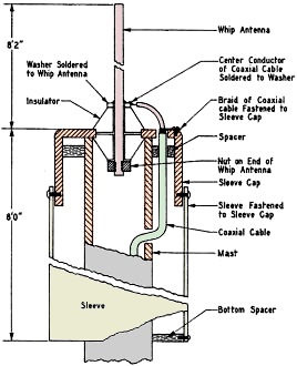
Fig. 2 - Constructional details of the antenna at W9YVZ.
Dimensions of whip and sleeve are for a resonant frequency of 28.6 Mc. The antenna
operates with a low s.w.r. from 28.2 to 29.0 Mc.; above 29 Mc. the s.w.r. rises
but for all practical purposes the system covers the entire 28.Mc. band satisfactorily.
Two blocks of wood are next whittled to serve as centering devices for the sleeve
section of the antenna. Both are of pine, varnished before installation, and lend
no support to the antenna. One piece serves to center the mast on the sleeve cap.
This piece in some cases may not be necessary as the mast may center itself on the
feed-through insulator in the sleeve cap. The other, or lower, block is mounted
at the base of the sleeve and maintains the sleeve in alignment with the mast. It
was found that without this lower block the wind blowing across the open end of
the sleeve section caused a low-pitched whistle to be set up by the sleeve hollow.
Until the cause of the noise was discovered the neighbors asked if the ghosts formerly
on their TV sets were now haunting the ham bands!
The antenna is fed by 70-ohm coaxial cable. For low-power work RG-59/U may be
used, but for higher power RG-11/U should be used. The RG-11/U has lower loss than
the RG-59/U and is recommended. The coaxial cable is fed through the lower hole
in the mast and is "fished" through the upper hole and through the hole in the sleeve
cap, About three inches of outer jacket is removed from the cable and the braid
fanned out from the cable and soldered to a lug on the sleeve cap. The center conductor
is then soldered to the washer of the whip section of the antenna.
The sleeve section is now slipped over the mast and screwed to the sleeve cap.
At this point it is a good idea to paint the sleeve, the sleeve cap and the mast.
Do not paint the sleeve cap insulator or lower sleeve spacer.
The antenna, now assembled, is ready for installation. The bottom end of the
mast section is placed in a hole drilled about four feet into the ground with a
post-hole digger. This depth is adequate to support the antenna and also permits
the mast to serve as a clothes post. Bricks and rocks are piled in the bottom of
the hole and a bag of ready-mix cement mixed up and poured into the bottom of the
hole. The balance of the hole is then filled with dirt. The antenna is self-supporting
and no guy wires are necessary.
The coaxial cable lead-in may be laid along the ground but the installation will
be made more complete by burying the cable in the ground from the antenna to the
shack. The trench may be dug with a trowel or lawn edger and need not be more than
a few inches deep enough to put the cable just under the sod of the lawn.
Results with this antenna have been excellent at W9YVZ. When the band is open,
east and west coasts and some DX is worked with good results and reports. When the
band is "dead" and only locals are coming through, contacts up to 100 miles with
reports of S8 to S9 are made. This was not possible with the horizontal antenna
previously used at this location. Mobile stations are easier to contact and the
range of operation with mobiles has been extended. The power run by W9YVZ is only
18 watts.
There have been many arguments about vertical vs. horizontal antennas on ten
meters. Here is a vertical coaxial antenna which, at least for the writer, has proved
itself superior to horizontal dipoles and yet is simple and inexpensive to construct.
* c/o American Phenolic Corporation, 1830 S. 54th Ave., Chicago 50, Illinois.
Posted July 22, 2022
(updated from original post on 11/8/2016)
|