|
October 1947 QST
 Table of Contents Table of Contents
Wax nostalgic about and learn from the history of early electronics. See articles
from
QST, published December 1915 - present (visit ARRL
for info). All copyrights hereby acknowledged.
|
This rather extensive article from a
1947 issue of QST magazine describes the method used by author Philip Erhorn
to experimentally (i.e. empirically) determine optimum spacing for the parasitic
elements of his antenna. Unless you have electromagnetic field simulation software
available for designing antennas, the procedure typically involves beginning with
published formulas for element length and spacing, then resorting to a cut-and-test
method of finding a combination that works best for your installation and goals.
Almost certainly no two Hams end up with identical configurations because differences
in terrain, physical obstacles, antenna height, soil conductivity, test methods
and available equipment, and ability to interpret results affect outcomes. Even
with software like "EZNEC" (free
as of January 2022) and more sophisticated professional programs like NI/AWR's "Analyst" and Keysight Technologies' "Momentum," significant variations can occur one an antenna is
deployed in an operational environment.
Element Spacing in 3-Element Beams
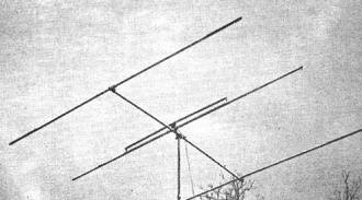
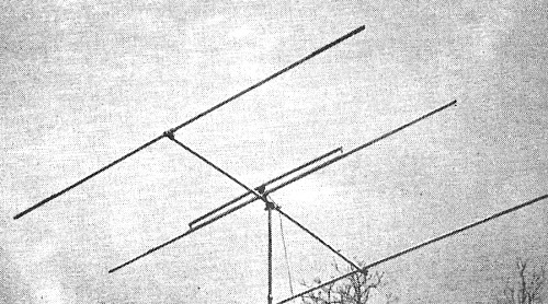
The all-metal array used in the tests. The spacings shown are
those determined by the author to be the optimum compromise: reflector 0.2 wavelength
and director 0.15 wavelength from the driven element. The shorting clamps on the
"T"-match were finally positioned eight inches either side of center to give the
lowest standing-wave ratio (1.75 to 1) with 70-ohm transmitting Twin-Lead.
Tests on Parasitic Arrays, with Particular Reference to Optimum Element Lengths
for Various Spacings
By Philip C. Erhorn, W2LAH
The results of this series of tests brings out the desirability of actual tuning
of an array as compared to putting it up "by formula." A tuning procedure that has
led to consistently good performance also is described.
The remarkable efficiency of the simple two-element parasitic beam antenna has
been proven by thousands of hams. Ask the man who owns one! But when you do, you'll
probably find that he is experimenting with a three- or four-element array, and
is having a lot of trouble answering the questions that seem to multiply with each
additional element. First and foremost, what are the optimum spacings for a three-element
beam? What formula should be used in setting up the element lengths? What can be
gained by tuning?
All these questions and more remained to be answered, and so, spurred on by many
QSOs on the subject, the literature was thoroughly culled for concrete information
in an effort to find a starting point for setting up the dimensions of a three-element
ten-meter array. The various formulas were set down and the element lengths figured
out so that they could be compared and perhaps averaged. But it was immediately
found that there was little similarity from one set of formulas to another.
And what about the new trend toward wide spacing? What about front-to-back ratios?
Since the questions were still piling up, it seemed that the only way to find out
some of the answers was to set up an experimental three-element array, make careful
tests for all of the commonly-used spacings, and then be governed by the results.
The procedure employed in these tests and the results are here presented in detail.
Equipment Used in Tests
All of the arrays were of "plumber's-delight" construction, as shown in the photograph,
utilizing 1 1/2-inch 24ST dural tubing for the elements, supporting boom and "T"-match.
The dural tubing was obtained cheaply from a junk dealer in 12-foot lengths, with
4-foot inserts for each end that fitted like a glove yet could be moved smoothly
for adjustment of element length. With the help of a friend, and using the shop
facilities of a local high school, several dural castings were made to be used in
securing the elements to the tubular boom. These castings were formed so that the
elements could be removed easily, or the casting and inserted element slid along
the boom and locked for spacing adjustments, Mechanically, everything turned out
to be simple, rigid and strong.
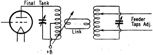
A portable transmitter, whose input was variable from a few watts up to 40 watts,
was used with a feeder-matching unit to facilitate loading changes. This feeder
or antenna tuning unit was simply an impedance-matching device between the final
tank and a so-called flat line. It proved to be very worth while in transferring
power efficiently from the final tank to the line. The circuit is given in Fig. 1.

Fig. 1 - Feeder-matching unit used in the tests. Loading
is determined by adjustment of link coupling and feeder taps, as described in the
Handbook.
A sketch of the field-strength antenna is shown in Fig. 2. The method used
in setting up the field-strength antenna served a double purpose. The length of
a resonant half-wave antenna was first determined by erecting the three-element
array on its mast, roughly tuning it by formula, and using it to excite a single
half-wave element (also 1 1/2-inch dural), and then tuning the half-wave for maximum
current. Since the element could not be broken in the middle, the thermomilliammeter
was inserted at the center of a simple "T"-match made of wire, and tapped out equally
near the ends of the element. Tuning this half-wave to resonance was rather critical,
in that the resonant point was extremely sharp.
With this half-wave antenna mounted on a short wooden 2 X 4, a close-spaced director
was added to it and tuned to give maximum current through the thermomilliammeter.
The forward sensitivity was increased thereby, and this make-shift array was used
as a field-strength indicator at a distance of about a full wave from the beam array.1
It was impractical to increase this distance because the writer had to work alone
and several thousand readings were to be taken. The addition of the director to
the field-strength antenna also helped to make it relatively insensitive to reflections
from near-by trees or buildings. All measurements were made with the beam and field-strength
antenna 20 feet above sandy ground and 7 feet above a wooden roof. Finally, the
new Micromatch2 circuit was constructed and tested, and proved to be
an excellent indicator of standing-wave ratios.
Tuning Procedure
Because the length of the boom was 12 feet over all, the first set-up used took
full advantage of this length, with the reflector spaced 0.2 wavelength and the
director 0.15 wavelength from the driven element, or symbolically R-0.2-A-0.15-D.
The driven element of the array was set at the just-determined resonant length and
left at that length for all subsequent measurements. The parasitic-element spacings
were based upon this length for two operating frequencies, 28.6 and 29.2 Mc.3
The reflector was first detuned by removing the sliding inserts in each end of
the 12-foot center section, and the director was set at the same length as the driven
element and pointed at the field-strength antenna. With power applied a field-strength
reading was noted. The director length was then shortened inch by inch until the
maximum reading was obtained (about double the reference value) and then fell off
as the length was reduced past the optimum point. The length for maximum gain was
not too critical.
With the director left at the adjustment for maximum forward gain, the reflector
was set at the same length as the driven element. As the field-strength meter immediately
went off-scale, power was reduced until the meter read about half-scale. The reflector
length then was increased inch by inch but showed no increase in field strength,
gradually falling off as the length was increased. The optimum length was coincidental
with the driven-element length, and was definitely not critical. It was then found
that the director could be lengthened slightly to produce a small increase in gain.
Next, with the beam reversed so that the reflector faced the field-strength indicator,
the reflector was again lengthened, until a minimum reading was reached. Lengthening
past this point caused the reading to increase again. Incidentally, it was necessary
to practically quadruple the power input to the transmitter to get any reading at
all off the back of the array for adjustment of the front-to-back (F/B) ratio. The
F/B ratio was excellent even with the reflector set for maximum forward gain, and
adjusting the reflector for best F/B ratio reduced the forward gain reading by only
a small amount.
It was now found that lengthening the director gave a small increase in forward
gain, but the F/B ratio was completely ruined. It was also found that the forward
gain could be slightly increased by shortening the driven element and retuning the
director. However, the F/B ratio was again ruined. These increases in forward gain
were so small as not to be worth while, in view of the much-poorer F/B ratio which
ensued.
An alternative method of tuning was tried which has been widely advocated. The
reflector was turned to face the field-strength antenna and detuned by removing
the sliding end inserts. The driven element was set to the determined resonant length
and the director tuned for minimum field strength. The director length was considerably
shorter with this method. Rotating the array 180 degrees disclosed an exceptionally
poor F/B ratio, particularly when the director was spaced at 0.2 wavelength. But
by tuning the reflector to the previously-determined length for best F/B ratio,
the forward gain was greatly increased and the F/B ratio was also greatly improved.
Then increasing the short director to the previously-found optimum length again
greatly increased the forward gain and had an extremely small effect upon the F/B
ratio. Now the lengths of all the elements were at the settings found in the first
procedure, and the alternative procedure was obviously not ideal.
Both the R-0.2-A-0.15-D and the R-0.15-A-0.2-D spacings were checked at 28.6
Mc. and at 29.2 Mc. and the values found at one frequency with a given spacing followed
closely in pattern for the other frequency. Here note that the spacing figures for
the lower frequency were also used at the higher frequency. This saved a lot of
time, particularly as the difference was very slight and was compensated for in
the element tuning. However, once the array was tuned up at either frequency, it
was found that sliding the parasitic elements toward or away from the driven element
produced an immediate and radical drop in field strength, this showing that the
tuning was optimum for a given spacing only. No unusual effects were noted except
in two cases to be pointed out later.
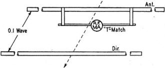
Fig. 2 - The field-strength indicating array. The elements
are 1 1/2-inch diameter tubing.
The standing-wave ratio (s.w.r.) was measured by means of the Micromatch and
was found to be almost 100/1 with 300-ohm Amphenol Twin-Lead for the line. No amount
of adjusting of the "T"-match could alter it, with the "T"-tubing the same diameter
as the driven element, spaced 2 inches between adjacent surfaces. However, changing
over to 70-ohm transmitting Twin-Lead brought it down to 20/1, and it was finally
reduced to 1.75/1 by easy changes in the positions of the shorting bars. The element
lengths were then checked again, but no revisions were necessary.
There was still one more method of tuning that had not been tried, but that was
used by some of the stations worked. In this case the transmitter was tied to the
field-strength array, and it was used to excite the beam, with the thermomilliammeter
connected in the center of the beam "T"-match. The transmitter power had to be considerably
reduced to get usable readings with this method. The driven-element length was left
unchanged, and the director tuned for maximum current through the meter, with the
beam facing the exciting antenna. Strangely, the director was lengthened to slightly
more than the driven-element length! The reflector length remained unchanged for
either maximum forward gain or best F/B ratio. The F/B ratio was very poor.
It was felt that this method was also not ideal.4
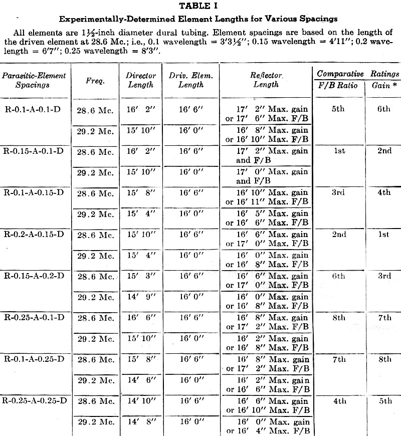
Close Spacing
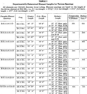
Table I - Experimentally-Determined Element Lengths for Various
Spacings
All elements are 1 1/2-inch diameter dural tubing. Element spacings are based
on the length of the driven element at 28.6 Mc.; i.e., 0.1 wavelength = 3' 3 1/2";
0.15 wavelength = 4' 11"; 0.2 wavelength = 6' 7"; 0.25 wavelength = 8' 3".
The next spacing to be tried was the popular close spacing, R-0.15-A-0.1-D. It
was decided that the original method of tuning the director with the reflector detuned
completely was not necessary and wasted some time, so all elements were set to the
same length as the driven element to start.
The director length was very critical. A change of only two inches made a big
difference in the field-strength reading, and the optimum director length was considerably
greater as compared to the wider spacings. The optimum reflector length also was
somewhat greater than any of the previous lengths, and the length for maximum forward
gain was also the correct length for best F/B ratio. Shortening or lengthening the
reflector immediately ruined the excellent F/B ratio. Any attempt to retune the
director showed a definite decrease in forward gain.
Now with the spacings reversed - that is, R-0.1-A-0.15-D - the same procedure
was used, with all elements set at the same length for the start. The director length
was found to be fairly critical and the reflector length very critical. A change
of only two inches produced a large change in both forward gain and F/B ratio. The
length of the reflector was slightly greater for maximum F/B ratio than for maximum
gain, but again the loss in forward gain at the setting for maximum F/B ratio was
small. The director length remained unchanged after the reflector was tuned, and
the length was fairly critical.
It was decided to see what unusual figures might evolve with a spacing of 0.1
wavelength for both director and reflector. Again, all lengths were initially set
at the length of the driven element. The director could be shortened a few inches
for a worthwhile increase in gain, and the length was fairly critical. Increasing
the reflector length by several inches also gave a good increase in gain, and the
setting was not very critical. It was then found that the optimum director length,
although unchanged, was now quite critical. The F/B ratio at this point was excellent.
However, increasing the reflector length gave a slight improvement in the F/B ratio
and had an unmeasurable effect upon the forward gain.
At the higher frequency, where the spacings were slightly greater, in terms of
wavelength, the director could be shortened to a point where the field strength
appeared maximum, and then further large decreases did not seem to have any effect
upon the forward gain. But after the reflector was tuned, the director assumed a
more natural length. This seemed to indicate that the spacing figures for such close
relative spacings should be figured carefully for optimum results.5
Broad-Banding
According to the Handbook, an array can be broad-banded by tuning the director
to a frequency differing from that of the other elements. So with the R-0.2-A-0.15-D
spacing, the array was tuned to resonance at 28.6 Mc. and the director was then
detuned to the length determined for 29.2 Mc. - 600 kc. higher in the band. The
field strength dropped off only about 1/8 of the reference value and the F/B ratio
was apparently unchanged.
However, with the R-0.15-A-0.1-D spacing, it was found that this type of broad-banding
seriously affected the forward gain, dropping the field strength to almost half
the reference reading. With the reverse spacing, R-0.1-A-0.15-D, the drop in gain
was also serious, but somewhat less.
Combined Spacing
The recent trend toward wider spacing of parasitic elements has also produced
arrays using combined close and wide spacing. The next logical step was to try some
such beam, and the following statements pertain to a spacing of R-0.25-A-0.1-D.
This particular set-up brought out some very interesting facts, since these spacings
happen to be the optimum for self-resonant parasitic elements used singly.
With all the elements set at self-resonance, it was found that the director could
be increased in length about one-half inch for a very small increase in forward
gain. This made it just longer than the driven element. The gain dropped rather
rapidly as the length was varied either way from this setting. The reflector length
was increased only two inches for a slight increase in forward gain. The F/B ratio
was rather poor, although increasing the reflector length another six inches improved
the F/B ratio somewhat. But it was still not as good as all other spacings so far
checked. The forward gain was not affected by the adjustment for best F/B ratio.
With the reflector tuned for maximum F/B ratio, the director then peaked at "self-resonance."
The reverse spacings, R-0.1-A-0.25-D, were the next to be checked, and it was
immediately noticed that with the elements all set to the same length as the driven
element, the wider-spaced element was automatically the reflector, until detuned.
However, progressive shortening of the director gradually increased the forward
gain, with the adjustment very uncritical over an unusually wide range. On the other
hand, the reflector length needed to be increased only two inches for maximum forward
gain and the peak was quite critical, the field strength dropping off rapidly on
either side. The director could now be lengthened by several inches for a fair increase
in forward gain. However, the F/B ratio was poor. Retuning the reflector for best
F/B ratio unfortunately resulted in a very serious drop in forward gain. Splitting
the difference between the two reflector lengths was only a fair compromise.
Wide Spacing
All the spacings in more or less common use, and that could be accommodated in
the 12-foot boom length, had now been tested, but one out-standing set of spacings
was yet to be investigated: . the all-wide-spaced array R-0.25-A-0.25-D. This might
give results quite different from any yet observed. So, with no little difficulty,
the boom was extended to allow an over-all spacing from reflector to director of
16 foot 6 inches. Wooden props had to be used to keep the elements from sagging
out of line in the experimental set-up. The elements were all set at the same length
as the driven element in the first step of the now-standardized tuning process.
The director then had to be shortened considerably to give the maximum increase
in field strength over the reference value. The optimum point was reasonably critical.
Now it was found that although the reflector length was not critical, it coincided
with the driven-element length as an optimum.
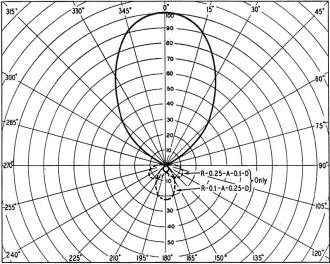
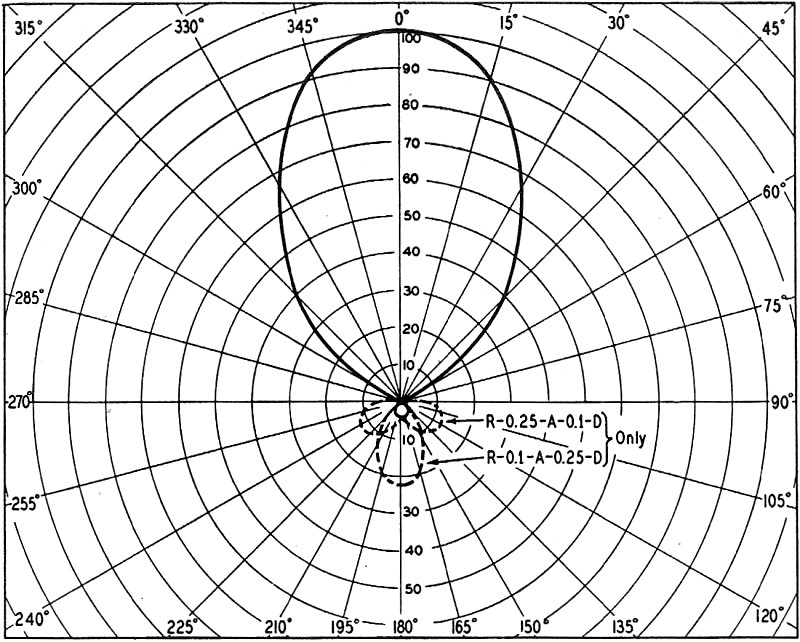
Fig. 3 - The forward field pattern shown is typical of all
the three-element arrays tested. The solid line is the pattern for the R-0.2.-A-0.15-D
antenna. On the relative scale with the forward field represented by 100, the rear
lobe with this antenna had a value of 2. Except for the two dotted-line patterns,
the rear radiation with all the antennas was below 5. All arrays were adjusted for
best front-to-back ratio in making the patterns.
At this point the F/B ratio was excellent, but a definite decrease in back radiation
could be secured by increasing the reflector length a few inches. The forward gain
dropped somewhat with the reflector adjusted for maximum F/B ratio, and continued
to drop gradually as the reflector length was increased considerably past this setting.
The F/B ratio was so good, however, that this large increase in reflector length
failed to affect it measurably.
In order to check the s.w.r., the "T"-match was tentatively set at the position
found to give the lowest s.w.r. for the other wide-spaced arrays, R-0.2-A-0.15-D
and reverse. The Micromatch was inserted in the line, and lo, the s.w.r. was only
1.1/1 without any further adjustment! The s.w.r. was checked again during a heavy
rainstorm, and although the 70-ohm Twin-Lead was soaked for half its 50-foot length,
the s.w.r. was unchanged at 1.1/1. With this all-wide-spaced array, the only critical
adjustment was the length of the director, and the only undesirable feature was
the ungainly length of the supporting boom.
Borrowing an idea from a well-known demonstration on v.h.f. beams, a large window
screen, 7 by 8 feet, was moved about between the array and the field-strength antenna.
Only when the screen was within 6 inches of the elements of either array and parallel
to them was any change in the field-strength reading observed. On the other hand,
interposing a resonant half-wave element anywhere between the two arrays caused
the field-strength meter to swing crazily.
Field Patterns
Although the forward gains of the various arrays can be rather roughly compared
by field-strength measurements in the plane of the antenna, the gain of the beam
at operating angles above the horizon can only be determined by methods beyond the
scope of most amateurs. The height above ground can be as important to the vertical
directivity as the yet-to-be-found optimum spacing. In comparing the forward gains
by field-strength measurements, many errors can be introduced by low radiation resistance
and high s.w.r.s. Simply having the same transmitter input for each comparison is
far from enough.6 It was therefore decided to make final comparisons
of the various arrays by taking field patterns of the direct radiation, adjusting
the transmitter loading so that each array gave the same reference reading on the
field-strength indicator. In this way no one array could have an unseen advantage
over another.
A circle was drawn on a piece of cardboard, with radials for every 15 degrees
of arc. This was slit and fitted around the pipe mast and secured to the edge of
the convenient rooftop. After the beam had first been aimed for maximum forward
gain, an indicator was attached to the mast and the compass card orientated. When
the mast was turned, the 15-degree divisions could be read off with good accuracy.
Field-strength readings were taken around the compass for each array and the points
then plotted on polar graph paper so that a pattern could be read. See Fig. 3.
Because the peak readings were the same for each array, the major lobes were
much the same in shape. There was enough variation to be indicative of which was
the sharpest and which was broadest. Also the backward lobes, if any, were directly
comparable in extent. See Table I.
These field patterns crystallized the findings of most of the previous tests.
Several important facts were quite obvious:
1) No one pattern was greatly superior to the others, when the main lobes were
compared for general sharpness.
2) Only the combination wide- and close-spaced arrays had a noticeable backward
lobe, with R-0.25-A-0.1-D showing a double lobe to the rear.
3) The R-0.1-A-0.1-D spacings had the broadest front lobe.
4) The most widely-used close spacings, R-0.15-A-0.1-D, had the best F/B ratio.
5) The wide-spaced arrays, R-0.25-A-0.25-D and R-0.2-A-0.15-D, had patterns that
compared with the best of the others.
6) The director should be spaced closer than the reflector for best F/B ratio
and highest forward gain, no matter what the relative spacings.
7) And according to (6) above and using (4) as a pattern, increases over the
basic R-0.15-A-0.1-D close spacing might well be made in steps of 0.05 wavelength
each, such as R-0.2-A-0.15-D and R-0.25-A-0.2-D.
Conclusions
Because only the direct radiation could be measured, it is not possible to specify
which set of spacings is best for low-angle radiation. But the data brought out
(and verified by the field patterns) did help to settle the question of spacing
from other viewpoints. In general, it was felt that while the close-spaced beams
exhibited excellent gain and F/B ratios, the low center impedance, narrow frequency
characteristics and feeding difficulties made a compromise spacing more desirable,
particularly the R-0.2-A-0.15-D spacing. This wider spacing retained an excellent
F/B ratio with no measurable sacrifice in forward gain, could be broad-banded or
used at frequencies widely separated from resonance without serious losses, was
easier to feed in regard to a really low s.w.r., and the over-all supporting boom
length was not ungainly.
No one formula was universally applicable in determining element lengths. Variable
factors such as tubing size and mode of construction made it necessary to establish,
by separate excitation, the resonant length of a half-wave as a working reference.
This was verified in attempting to tune a neighbor's close-spaced beam of entirely
different construction and element sizes. There was no critical adjustment and no
real gain apparent when the driven-element length was set by formula. The beam just
wouldn't seem to tune. Then the parasitic elements were removed in order that the
driven element could be tuned to the operating frequency by separate excitation.
With the parasitic elements replaced, they not only were rather critical of adjustment,
but immediately showed a tremendous increase in gain over the driven element alone.7
Checking all s.w.r.s with the Micromatch disclosed inherently higher values with
one or both elements close-spaced than with the wider spacings. This was no doubt
caused by the decreased radiation resistance and the fact that all adjustments of
the "T"-match were critical for close spacing. Five close-spaced beams were tested
at as many different locations, all using different arrangements of the "T"-match.
Contrary to most recent published data, it was impossible to get a low s.w.r. on
any of them when fed with 300-ohm Twin-Lead or open-wire line. Changing to 70-ohm
Twin-Lead in three cases brought the s.w.r. down to more reasonable values. But
only with the wider spacings was it possible to get the s.w.r. down to 2/1 or better.
Many stations worked during changeable band conditions verified the efficiency
of the well-matched R-0.2-A-0.15-D array. S8 reports were received on several occasions
from South America with the beam 20 feet off the ground and using 15 watts input
on 'phone. The West Coast was worked consistently at either end of the 'phone band
with the same low power.
The use of coax cable for feeding low center-impedance arrays is also generally
indicated, but it has fallen into disfavor because of its unbalanced characteristics.
This unbalance can be readily circumvented by using some form of "bazooka" or line
balancer, but a simpler method would be the use of two pieces of coax side by side
in the manner of a two-wire line, with the shields tied together. The resulting
series impedance would still be reasonably low, and of course the line would be
completely impervious to weather conditions. In any event it is recommended that,
regardless of the method of feed, every effort be made to reduce the s.w.r. to a
minimum. Line radiation caused by a high s.w.r. can only result in poor transfer
efficiency and an unsymmetrical beam pattern.
About the Author
After a daily stint studio-controlling soap-box operas for CBS, New York, it
must be welcome relief for W2LAH to carryon his beam experiments in the peace and
quiet of the busy 10-meter band. Besides his b.c. engineering duties, Philip C.
Erhorn's radio interests are DXing and v.h.f. experimenting. A member of the Garden
City Radio Club, W2LAHl is holder of an ARRL Public Service Certificate for notable
work during the 1938 Long Island hurricane.
1 The validity of measurements made this close to the antenna may be questioned,
in view of the fact that the induction field is not negligible at this distance,
the behavior of the ground-reflected wave is uncertain, and there is a distinct
possibility that the pick-up antenna tends to become part of the antenna array being
tested. To offset one of these factors, it may be observed that the use of a director
with the pick-up antenna will tend to discriminate against the ground-reflected
ray, and also that the inherent directivity of the beam under test will tend to
reduce the amplitude of the reflected ray at such a short distance. Also, coupling
between the pick-up antenna and the beam under test presumably would be detectable
by a change in the input impedance of the beam when the pick-up antenna is removed,
and the author states that the presence or absence of the pick-up antenna caused
no observable change in the standing-wave ratio. The adjustments achieved by the
procedure outlined have led to good results in actual communication. - Editor
2 Jones and Sontheimer, "The Micromatch," QST, April, 1947.
3 The usual method is to calculate the spacings on the basis of free-space wavelength,
since all theoretical studies and calculations, as well as published data, are on
this basis. The author's spacings are about 4 per cent less than the free-space
values. - Editor
4 Adjusting the beam while using it as a receiving antenna is based on the assumption
that the tuning conditions for optimum gain and front-to-back ratio are the same
for receiving as for transmitting. This is true only when the antenna is delivering
maximum power to a load - i.e., is terminated in a resistance equal to its own impedance.
Since this impedance varies with different tuning conditions the necessary readjustments
for maximum output after each change become rather tedious. - Editor
5 An alternative explanation is that at such close spacing the coupling between
elements is so tight that tuning of one has a large pulling effect on the tuning
of the other. It is worth noting that in the two-element case the director gain
shows a marked peak at 0.1-wavelength spacing and the radiation resistance has a
similarly sharp minimum. Both gain and resistance are less critically a function
of spacing at wider spacings. - Editor
6 This same statement is also true, of course, of measurements made on a given
antenna when the tuning is varied by adjusting element lengths, because the tuning
varies the impedance of the driven element. To be certain that the same power is
going into the antenna under all conditions it would be necessary to rematch (at
the antenna) so that the s.w.r. is the same at every measurement. Otherwise considerable
error may be introduced. - Editor
7 No satisfactory explanation is at hand for this apparently critical behavior
of the driven element; it is hard to reconcile it with the fairly wide-band acceptance
of the wider-spaced systems, inasmuch as the detuning from the resonant frequency
in these tests represents a greater percentage change than the differences between
most of the published formulas for resonant frequency. Nor is there any obvious
theoretical reason why the driven-element length should have to be exact, aside
from matching difficulties that prevent efficient power transfer from the transmitter
to the antenna. - Editor
Posted September 19, 2022
(updated from original post
on 5/23/2016)
|