April 1932 QST
 Table
of Contents Table
of Contents
Wax nostalgic about and learn from the history of early electronics. See articles
from
QST, published December 1915 - present (visit ARRL
for info). All copyrights hereby acknowledged.
|
You always need to pay careful attention
to "breakthrough" type articles when they appear in April issues, since many magazines
have a tradition of burying an "April Fools' Day" item without notice. This April 1932
issue of QST magazine seems to be legitimate. The term "lycopodium pattern" aroused
my suspicion, but it turns out to refer to a pattern of vibration that resembles
the needle orientation of certain pines and cedars. As radio frequencies continued
to increase during the early years of "wireless" development, the use of quartz
crystals as a stable reference source ran into a physical limitation because as
crystal slices reached a certain thinness, overtone and subharmonics appeared that
caused problems in circuits. A new mineral called tourmaline saved the day. With
an elasticity much greater than quartz, tourmaline is able to vibrate at higher
fundamental frequencies for a given thickness. Since that time, science has provided
the means for utilizing the much more abundant quartz crystals in overtone modes
so that tourmaline is not required. At the time, though, it was a much-welcomed
alternative.
Fundamental Crystal Control for Ultra-High Frequencies
Tourmaline Oscillators for Wavelengths Down to 1.2 Meters
By Harald Straubel
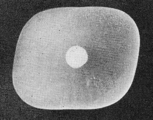
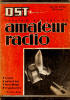
Fig. 1 - Lycopodium pattern of transverse oscillation of
a quartz plate cut so that vibrations starting at the center are reflected simultaneously
from the circumference. The powder thus collects at the central nodal point.
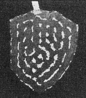
Fig. 2 - Lycopodium pattern on the surface of a "raw" tourmaline
crystal plate that was cut perpendicular to the axis.
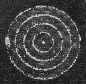
Fig. 3 - When the crystal of Fig. 2 was made circular
the pattern of the oscillations became more symmetrical, as shown by the concentric
rings of the lycopodium collected at the nodes.
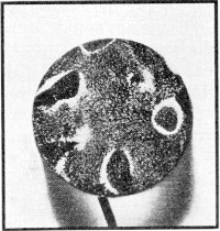
Fig. 4 - Contrast this pattern of a disc-shaped quartz oscillator
with those of the tourmaline shown in Fig. 3.
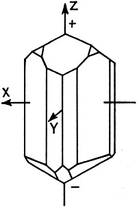
Fig. 5 - Ii the tourmaline crystal the optic and electric
axis have the same direction.
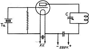
Fig. 6 - The tourmaline controlled oscillator circuit. It
is of the same type as the familiar circuit generally used for quartz crystal control.
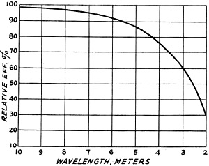
Fig. 7 - Performance curve for an RE 134 valve with tourmaline
crystals of the same diameter but of different thicknesses to give various wavelengths.
The efficiency decreases rapidly at the shorter wavelengths.
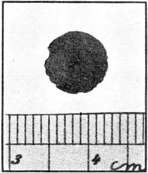
Fig. 8 - An ultra-high frequency tourmaline crystal that
was cracked near the edges from overloading without impairing its operation. The
diameter of this plate is 8 millimeters (0.312 inch).
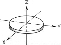
Fig. 9 - The tourmaline plate with respect to its three
axes. The major surfaces are perpendicular to the optic (Z) axis and parallel to
the plane of the X and Y axes.
Here is confirmation of exciting rumors that have been coming through from Germany
since last fall. Practicable fundamental crystal control at the frequencies too
high for quartz, has arrived. Tourmaline crystal does the trick. The pleasure of
presenting this article is the keener because of the friendly cooperation of the
A.R.R.L.'s sister societies, the D.A.S.D. and the R.S.G.B., that have brought it
to us. The connection with the D.A.S.D. of Dr. Straubel, the author, and that with
the R.S.G.B. of Mr. Pilpel, the translator, make this contribution a fine feather
in the cap of amateur radio. - Editor.
The method of fundamental crystal control which has been used so far presents
difficulties on frequencies higher than 6000 to 7500 kc. because very thin quartz
oscillators produce side tones on several neighboring frequencies. This multiplicity
of oscillations is noticeable even on longer waves but can be suppressed by cutting
the quartz plate in a suitable shape. Fig. 1 shows such a plate. The surface
and sides are ground so that all oscillations starting at the center will be reflected
at the same time from the circumference of the crystal. The radius of the curves
at the corners depends on the square root of the modulus of elasticity of quartz.
If this plate is excited on its fundamental frequency, the whole plate oscillates
in all directions. Lycopodium powder, uniformly distributed over the crystal plate,
is therefore concentrated at the middle point, which is the nodal point of the whole
disc.
For considerably higher frequencies than 6000-7500 kc. crystal-controlled short-wave
transmitters nowadays do not often use this method, but employ quartz crystals with
fundamental frequencies such as 3000 to 1500 kc., with frequency multiplication;
that is to say, one uses harmonics of the crystal oscillator and amplifies them.
An installation of this sort becomes very cumbersome and complicated when used on
the ultra short waves because the harmonics are so weak that amplification must
take place after every frequency doubling before further frequency doubling is practicable.
If it were possible to construct fundamental oscillators for such short waves,
the installation would be extraordinarily simplified.
Tourmaline Crystals

The tourmaline crystal controlled oscillator operates at 75 megacycles (4 meters)
with the stability and other characteristics of quartz-crystal controlled oscillators
operating at much lower frequencies. Imagine the number of frequency multiplying
stages that would be necessary to duplicate its performance with quart-crystal control!
(left)
On the above-mentioned grounds, quartz is unsuitable for short-wave fundamental
control. The author has found, however, that a tourmaline crystal produces considerably
more uniform oscillations than quartz. It was noticed even with a "raw" crystal,
a plate simply cut perpendicular to the optical axis, that on exciting the longitudinal
oscillations, extraordinarily uniform transverse oscillations resulted, as shown
in Fig. 2.
The piezo-electric constant of tourmaline is
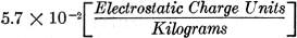 , ,
i.e., about 10% less than quartz.
If, in spite of the smaller constants and the irregular natural formation of
this crystal, particularly easy oscillations are noticeable, it is highly probable
that this is because there is considerably less tendency to side-tone oscillation.
Actually, in the natural crystal only a few symmetrical side tones could be detected
and the frequencies of these were far removed from the fundamental.
From these results it can be assumed that the oscillating properties even of
such a thin crystal will remain constant, as they must do if it is to be used for
fundamental control of ultra short-wave transmitters. A further advantage for the
production of very high frequencies lies in the high speed of sound, necessitated
by the extraordinarily large elasticity modulus of 1,600,000 kilograms per square
centimeter in the direction of the optical axis. Tourmaline, therefore, supplies
a frequency 35% higher than quartz of the same thickness, the constant being 80
meters wavelength per millimeter thickness.1
Circuit and Tubes
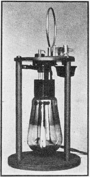
A circuit for the production of the oscillations is shown in Fig. 6, while
the photograph shows the actual transmitter for use on 7 meters and employing 5
watts. The simplicity of construction and absence of any type of screening are noticeable.
For waves down to 2 meters (150 mc.) ordinary detector or power valves were used
(such as Telefunken RE 084 or RE 134), but for shorter waves a special short-wave
valve was employed, the Valvo S 0401. For longer waves of 5 meters and upwards,
a larger valve was found suitable, the RS 241, which is similar to the American
Type '10 and the Philips TB 04/10. It was noticed that, as is usual with all self-excited
transmitters, the higher the frequency the lower the efficiency, oscillation eventually
ceasing altogether. Fig. 7 shows the performance of an RE 134 valve. The reason
for this is partly the large self-capacity of the crystal which, for a given valve
capacity, upsets the phase of the reaction on short waves to such an extent that
the crystal no longer oscillates. The crystal then works only as short-circuit capacity
while the valve either oscillates unstabilized or ceases to oscillate altogether.
This can be avoided by reducing the capacity of the crystal, which can be done only
by decreasing the diameter. An increase in the diameter does not enable the crystal
to stand a greater load on these ultra short waves, however.
Suitable Mountings
The electrodes next presented certain difficulties. Silvering,2 such
as used in thick oscillators, must be omitted as this affects the fundamental frequency
of the thin plate quite considerably and a great load will cause peeling, although
the oscillator remains undamaged. Therefore, silvering was dispensed with and perfectly
level electrodes were used. Even slight unevenness of the electrodes caused certain
parts of the crystal to melt and become disintegrated. Splintering, such as occurs
with quartz, was never experienced.
By using perfectly plane electrodes the load on the crystal could be considerably
increased. Working temperatures of more than 100° Centigrade did not affect the
operation in any way. Great overloading (crystal 8 mm. diameter, RS 241 Valve with
350 volts plate potential) once caused the edge of the crystal to crack without
affecting the middle portion or causing the efficiency to decrease materially. (Fig. 8).
When the crystal was in a horizontal position, no extra weight was placed upon
the electrodes. Although an additional weight reduced the crystal's controlling
properties, it was possible, in the cases of crystals of larger diameter (12 mm.),
to subject them to pressures up to 500 grams per square centimeter before they stopped
oscillating. In order to render them safe from shocks and vibrations, a light spring
was always used to supply pressure.
Performance
With the 75-mc. transmitter depicted experiments were carried out to determine
the actual degree of frequency stabilization obtainable. The modulated transmissions
were received on a simple detector with regeneration over a distance of 1 kilometer
although no aerial was used for either transmitting or receiving. As far as the
transmitter was concerned, no hand-capacity effects were noticed; but when the hand
was placed near the inductance, reception was louder owing to the body acting as
a capacity-coupled aerial. Only when the coil was actually touched did oscillation
cease, to recommence immediately on the same frequency when the hand was removed.
This was particularly noticeable when the transmitter was keyed in the plate circuit.
The heterodyne note as heard in an oscillating receiver was absolutely pure on the
frequency of 75 mc. (4 meters) and showed d no frequency change whatsoever, better
than could be obtained when using a 7500-kc. quartz crystal. The well stabilized
transmitted frequency in every case could be received on the detector with regeneration
and without the need for the broad resonance curve of a super-regenerative receiver.
By varying the condenser C (Fig. 6) no jumping in frequency could be noticed.
Naturally, the frequency of the tourmaline, just as that of quartz, was affected
by varying the tuning of the plate circuit, but frequency jumping never took place.
To obtain this condition, however, perfectly plane parallel crystal surfaces are
necessary.
The temperature coefficient of tourmaline oscillators is about 10% greater than
the average of quartz and is negative. Repeated measurements in the region of 20°
to 60° Centigrade showed this coefficient to be 46.6 parts in a million per degree
Centigrade. For an accurately constant frequency one must use a thermostat and heater,
the cost of which is inconsiderable in comparison with the amount saved by the elimination
of frequency-doubling and amplifying stages, and the simplification of the installation.
For simple transmitters one can easily dispense with temperature control. The frequency
change of tourmaline is always in proportion to the temperature variation.
Fig. 9 shows how the crystal plate is cut from the actual crystal. The
position of the different axis is the same as in Fig. 5. Most suitable tourmaline
crystals are found in Brazil and South Africa.3
In conclusion, I wish to offer my thanks to the firm of Carl Zeiss, Jena, Germany,
for help in my experiments. In particular, without their great interest it would
have been impossible to overcome the difficulties in construction of the shortest
wave oscillators for 1.2 meters.
1 Converting to the English system and in terms of frequency,
t=146.25f, approximately, where t is thickness in inches, and f is frequency in
kilocycles. The thickness dimension is parallel to the Z axis for tourmaline whereas
it is generally parallel to either the X or Y axis for quartz. - EDITOR.
2 Cf. Parsons, "Silvering Electrodes on Quartz Crystals," QST,
March, 1932. - EDITOR.
3 We understand that the common black variety, known as
schorl,
is generally unsuitable. - EDITOR.
Posted May 6, 2021
(updated from original post on 4/18/2013)
|