February 1943 QST
 Table
of Contents Table
of Contents
Wax nostalgic about and learn from the history of early electronics. See articles
from
QST, published December 1915 - present (visit ARRL
for info). All copyrights hereby acknowledged.
|
The word "transformer" in the title for this1943
QST magazine
article does not refer to a mutual inductance transformer, but an impedance transformer
for matching transmission lines to antennas (or anything else for that matter).
Author T.A. Gadwa gives examples of impedance-matching circuits both for when
the antenna impedance is lower than the characteristic impedance of the transmission
line and when the antenna impedance is higher than that of the feed line. "L," "pi,"
and a couple other circuit configurations are covered. Equations are also given. An Impedance-Matching
Transformer Tutorial
A Simple Method for Matching the Antenna to the Transmission Line
By T.A. Gadwa, SC.D., W2KHM
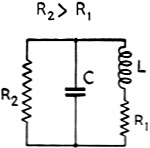
Fig. 1 - Parallel-resonant circuit with equivalent series
and parallel resistances.
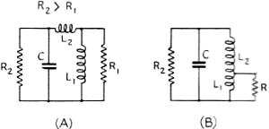
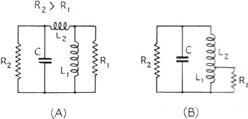
Fig. 2 - An impedance-matching circuit using series or tapped
inductances.
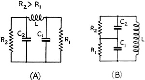
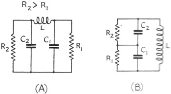
Fig. 3 - The pi-section filter, another type of impedance-matching
circuit.
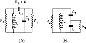
Fig. 4 - These circuits resemble those of Fig. 2 with
L and C interchanged.
While those of us at home don't have many opportunities these days to try tuning
up antenna systems, the method described in this article will some day be useful
to us. At present, it can be applied to WERS communication, design data for a suitable
coupler being included in the article.
Any simple and inexpensive method of coupling an antenna to a transmission line
always is attractive to amateurs. Numerous articles on untuned feeders have outlined
their advantages - lower losses, reduced feeder radiation and operation independent
of line length. An antenna placed in a favorable location and supplied power by
untuned feeders or transmission lines is frequently desirable, but coupling one
end of the transmission line to the plate circuit and the other to the antenna does
not solve the problem satisfactorily. To transfer power most efficiently on such
a transmission line, the load resistance must equal the generator resistance. This
means that power is absorbed by the load and none is reflected back to the sending
end to produce standing waves. If the termination differs from this load resistance,
standing waves appear on the line, representing wasted power that never reaches
the antenna. The character of standing waves for various types of loads has been
described previously1 and may be reviewed for reference purposes.
A transmission line of two parallel conductors has a characteristic impedance
which is determined by the physical dimensions of the system: diameter of the conductors,
their spacing and the insulation or dielectric. The equation for calculating the
impedance of an open-air two-wire parallel line is:
Ro = 276 log 2S/D (1)
where Ro = characteristic impedance of the line in ohms
S = spacing between conductor centers in any units
D = diameter of conductor in same units
Impedance Transformation
In come cases, the impedances of an antenna and transmission line are not equal
and some sort of transformation must occur before the load can be matched to the
line. It is possible to convert an impedance to a higher or lower value by utilizing
a circuit known as a filter, network or impedance transformer, composed only of
inductances and capacitances. When a filter of suitable design is inserted between
the antenna and transmission line, the load presented to the line will be equal
to the line impedance, and an impedance match for a flat line is possible. A parallel-resonant
circuit of inductance, capacitance and resistance, such as is shown in Fig. 1, has different impedances between various points of the circuit. The impedance
between any two points can be found by combining the series and parallel elements
in the usual manner. A pi-section filter will accomplish the same transformation,
which is equivalent to tapping the antenna across a portion of the inductance or
capacitance. These arrangements, shown in Figs. 2, 3 and 4, are not recommended
since they require one more element than the circuit of Fig. 1; also, it is
impossible to obtain a correct impedance transformation for certain combinations
of inductance and capacitance because of insufficient coupling. The impedance transformer
should exhibit pure resistance at its terminals, and Everitt2 has shown
what the values of the inductive and capacitive reactances should be to satisfy
this condition. Equations which have been used in previous QST articles,3,
4, 5 are:
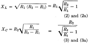 where XL = inductive reactance in
ohms where XL = inductive reactance in
ohms
XC = capacitive reactance in ohms R1 = input
or output resistance R2 = output or input resistance L = XL/2πƒ (4)
C = 1/2πƒXC (5) ƒ = frequency in cycles per second
L = inductance in henrys C = capacitance in farads
A resonant antenna can be connected to one pair of terminals and its effective
impedance at the second pair of terminals changed to equal that of the line. The
antenna behaves like a series resonant circuit and is a pure resistance at resonance.
It is reactive off resonance - capacitive at frequencies below resonance and inductive
at frequencies above resonance. For the case where the resistance of the antenna
is lower than that of the transmission line, the circuits in Fig. 5 can be
employed. Circuits in Fig. 6 are used when the antenna resistance is higher
than the line impedance. Symmetrical arrangements of the circuits for connection
to a two-wire line are shown in Figs. 5-C, 5-D, 6-C and 6-D. In Figs. 5-C and 6-C,
one-half the total inductance is put in each leg when the coils are not inductively
coupled. In Figs. 5-D and 6-D, one fourth the total inductance (half the total number
of turns) is put in each leg when the coils are inductive coupled.
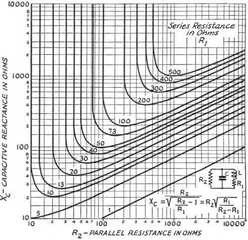
To aid in the solution of equations (2) and (3) curves are presented in Figs.
7 and 8. From the inductive and capacitive reactances, the inductance and capacitance
can be determined from equations (4) and (5). From the inductance, the coil diameter,
length of winding and number of turns may be found by the usual formulas or from
a Lightning Calculator.
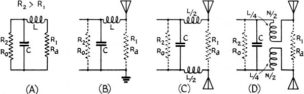
Fig. 5 - These impedance-matching circuits are used when the antenna resistance
is lower than the characteristic impedance of the transmission line.
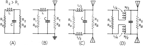
Fig. 6 - Circuits for use when the antenna resistance is higher than the
line impedance.
A Practical Example
To illustrate the various steps in the calculation, a typical case is solved.
It is desired to match the resistance at the center of one element of a 2-element
close-spaced 1/2-wavelength antenna at 14.2 Mc. to an open-air parallel 2-wire line
of No. 14 wire, with 6-inch spacing between wires. The characteristic impedance
of the line is obtained from equation (1).
Ro = 276 log (2 X 6/0.064) = 276 log (188) = 276 X 2.275 = 625 ohms
The antenna resistance may be assumed to be equal to 13 ohms. Since the line
impedance is higher than the antenna resistance, a transformer of type shown in
Fig. 5 must be employed. The inductive reactance from equation (2a) is
XL = 13√(625/13 -1) = 13 x 6.86 = 89.2 ohms
The required inductance, from equation (4) is
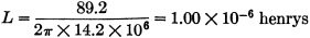
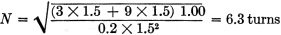
or 1.00 microhenry. Using the Handbook formula
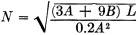
where N = number of turns
A = diameter of coil in inches (let A = 1. 5 inches) B = length of coil in
inches (let B = 1.5 inches) L = inductance in microhenrys
Within small limits, the inductance can be increased by spacing the turns closer
together and decreased by spacing them farther apart. Antenna material is satisfactory
for the coil, although heavier wire or copper tubing will keep the losses to a minimum.
The capacitive reactance, from equation (3a) is
XC = 625 / √(625/13
-1) = 625 / 6.86 = 91.1 ohms
The required capacitance, from equation (5), is
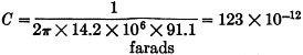
or 123 micromicrofarads. The voltage across the condenser is relatively low because
of the low impedance involved. Receiving type condensers are satisfactory, since
the plate spacing need not be large for most amateur powers. A two-section stator
with sections in series is desirable because this construction eliminates losses
in rotor connections. For 300 watts through a 625-ohm line, the voltage is
E = √(PR) = √(300 x 625) = 433 volts r.m.s.
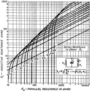 Fig. 7 - Parallel resistance vs.
inductive reactance for various values of series resistance.
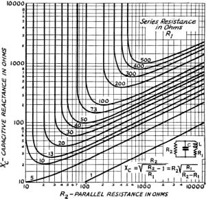
Fig. 8 - Parallel resistance vs.
capacitive reactance for various values of series resistance.
The peak is 433 X 1.414 = 610 volts and on 100 percent modulation the peak is 610
X 2 = 1220 volts.
The tuning unit must be protected from the weather. One version of such an impedance
transformer is illustrated in the photograph. The coil and condenser are mounted
in a weather-tight box made of quarter-inch tempered Masonite, with feed-through
terminals brought out through the sides for the line and similar terminals at one
end for the antenna.
Interference with the antenna radiation field by matching stubs, quarter-wave
sections and delta matching sections are avoided when the transformer is used, since
the transformer is concentrated in a much smaller space. The frequency response
of such a low-Q parallel circuit containing a series resistance is broad enough
to be used to advantage with close-spaced antenna elements having a sharp frequency-response
characteristic. Its application is essentially to one-band antennas since impedance
transformation is dependent upon the frequency of operation. It must be emphasized
that one and only one combination of inductance L and capacitance C will match a
given antenna resistance to a given line. As the ratio R2/R1 approaches
unity, XL approaches zero and XC approaches infinity; that
is, the inductance and capacitance both become smaller. The resonant frequency of
L and C without R1 may be considerably higher than with R1
in the circuit.
Adjustment
It is highly desirable to be able to tune
the unit when it is in its operating position at the antenna. This may be done by
varying the capacity until maximum antenna current is shown by an r.f. ammeter or
lamp bulb connected in the antenna at the junction to the transformer. Alternatively,
one may adjust for minimum line current at the line junction to the impedance transformer.
Where this is impossible or inconvenient, it is permissible to tune the coil and
condenser to resonance before connecting the antenna and transmission line. Since
the resonant frequency of the coil and condenser alone always is higher than with
the antenna in the circuit, the capacity is then reduced sufficiently to compensate
for the insertion of the antenna when the unit is in operating position. If the
antenna is resonant and the correct values of inductance and capacitance are employed,
the line will be correctly terminated. A constant current at all points along the
line, or a slight increase of current toward the transmitter or sending end, is
the final test of a perfect impedance match.
A thermomilliammeter connected across a portion of one feeder line at various
positions is a good indicator of standing waves. A flashlight bulb connected across
a short length of one feeder is also a good current indicator and is inexpensive.
The bulb should be shielded to direct the light to the observer so that the neighbors'
curiosity will not be aroused by night operation. If bulbs are permanently located
at intervals of 1/16 wavelength along the line, starting from the antenna, the brilliancy
vs. position shows the location of maximum and minimum line currents or standing
waves.
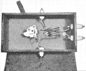
Suggested construction of an impedance-matching transformer for
suspension from an antenna. The condenser is controlled by the arm projecting toward
the upper left. A pulley could he used for adjustment from the ground.
If the antenna is nonresonant, its length must be adjusted or tuned to resonance.
Excite the antenna parasitically and obtain maximum antenna current by tuning. Noting
the position of the standing waves on the transmission line, as outlined in the
article on standing waves,1 also is recommended. One exception must be
observed because the resistance across the terminals of a parallel-resonant circuit
increases when the series resistance decreases. In other words, the load resistance
presented to the line is increased for a decrease in antenna resistance and, conversely,
the load resistance presented to the line is decreased for an increase in antenna
resistance. This may be understood by analyzing the approximate relationship that
holds for a parallel-resonant circuit of low series resistance or high Q.
R2 = L / (C x R1)
This is true when R1 is relatively small and is approximately so for
higher values of R1. It means that the parallel impedance is increased
by using larger inductance L and a smaller capacitance e (increasing L/C ratio),
and by reducing the series resistance R1. Conversely, the parallel impedance
is decreased by using a smaller inductance L and a larger capacitance e (decreasing
L/C ratio) and by increasing the series resistance R1. The parallel resistance
always is greater than the series resistance.
If the antenna is resonant but incorrect values of inductance and capacitance
are used in the impedance transformer, a current loop or node will appear near the
1/4 wavelength point measured along the line from the transformer. If a current
loop or maximum occurs at this position the terminating resistance is too high,
and a smaller inductance L and a larger capacitance C are required. If a current
node or minimum occurs near the 1/4 wavelength position, the terminating resistance
is too low and a larger inductance L and lower capacitance C are required.
If the antenna and line resistances are known, the ratio of the line and antenna
currents for an impedance match can be calculated from the square root of the antenna-to-line
resistance ratio. This is based upon the assumption that the power input to the
transformer equals the power output; i.e., that the losses in the transformer are
negligible.
P = I2R = I12R1 = I22R2
or
I1 / I2 = √(R2 / R1)
If an r.f. ammeter is available, measurement of the antenna and line currents
will reveal the correct impedance match from their ratio.
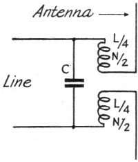
Fig. 9 - This circuit is used for matching a half-wave antenna
to a line having an impedance of the order of 500 ohms. Constants for 114 Mc. operation
are given in the text.
With 2 1/2 meters active for civilian defense, transmitting antennas and associated
problems are under consideration once again. A design is given in Fig. 9 for
matching a half-wave antenna at 114 Mc. to an open-air 2-wire line of No. 14 wire
spaced 2 inches:
S = 2 inches spacing D = 0.064 wire diameter, inches R2 =
495 ohms, line impedance R1 = 73 ohms, antenna resistance ƒ
= 114 X 106 cycles per second XL = 175.8 ohms L =
0.245µh. A = 1 inch (coil diameter) B = 1 inch (coil length) N
= 3.8 turns N/2 = 1.9 turns XC = 206 ohms C = 6.8 µµfd.
It is hoped that this method will not be overlooked when considering the problem
of matching the antenna to the transmission line. Because of its simplicity, it
might well be adopted by the amateur radio fraternity.
1 Gadwa, "Standing Waves on Transmission Lines," December, 1942, p.
17. 2 Everitt, Communication Engineering, p. 75. 3
Andrews, QST, October, 1939, p. 39. 4 Plotts, QST, November, 1941,
p. 15. 5 Roberts, QST, January, 1928, p. 43.
Posted June 25, 2021
(updated from original post on 6/13/2013)
|