|
September 1950 QST
 Table
of Contents Table
of Contents
Wax nostalgic about and learn from the history of early electronics. See articles
from
QST, published December 1915 - present (visit ARRL
for info). All copyrights hereby acknowledged.
|
Complete with all the nitty-gritty
details and necessary formulas for designing an inductive loop coupler for a rotating
antenna is this 1950 QST magazine article by Mr. Robert Mumma. Such a device is useful when you desire
a steerable antenna that prefers not to or cannot accommodate a section of coaxial
cable interfacing the fixed mast to the rotating antenna. It is rare that such a
requirement is found, since installing a set of limit switches to prevent the cable
from wrapping itself around the mast is relatively simple to implement. However,
if you want a system that continually rotates while searching for or broadcasting
signals, then something like this is needed. A radar antenna is a prime example,
as would a search and rescue operation using a directional antenna listening to
distress calls be another. There is also a "cool factor" that might cause you to
build and install one.
Another Inductive Coupling System for Rotary Beams
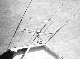
The dual beam for 20 and 10 meters. A "T'' match is used on the
20·meter driven element, while the 10-meter antenna is fed through a delta match.
Both antennas are inductively coupled to 300-ohm transmission lines.
A Coupling Method That Is Independent of the Matching System
By Robert E. Mumma, W8ORI
In the usual inductive coupling system for facilitating the rotation of beam
antennas the output loop is part of the driven element.1
There are many times when it is not convenient to make the output loop a part
of the antenna system - for instance, when the" plumber's delight" type of beam
is used. The coupling loop design to be described has been adapted so that the loops
can be inserted anywhere in a transmission line carrying r.f. power. It consists
of a single-turn input or primary loop and a single-turn output or secondary loop,
shown as Lp and Ls in Fig. 1. Each loop is tuned with
a variable condenser. The transmission line from the transmitter is connected across
the tuning condenser Cp for the primary loop, and the transmission line
to the antenna is connected across the tuning condenser Cs for the secondary
loop. In both cases a balanced type of transmission line is shown.
The design of this antenna coupling system is easily followed by means of an
example. Suppose that the system is to be designed for your latest 20-meter three-element
beam, which is tuned to 14.2 megacycles and is being fed with 300-ohm Twin-Lead.
Experience has shown that a Q between 5 and 10 for the coupling loops will bring
the dimensions within reason and make the tuning broad enough to cover the entire
band. Since we must start with some number, let us assume that the Q is 5.
The equivalent circuit for each of the loops in Fig. 1 is shown in Fig. 2.
L is the inductance of the loop, C is the capacitance of the tuning con-denser,
and R is the impedance of the transmission line, which is assumed to be a pure resistance.
 (1)
(1)
When R is 300 ohms and Q is 5, X will be 60 ohms. The losses in the loop and
in the condenser are assumed to be negligible in comparison with the 300 ohms shunting
the tuned circuit. With these loops tuned to resonance XL and XC
will both be 60 ohms. Then
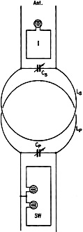
Fig. 1 - The inductive coupling system, showing the current
indicator (I) and standing-wave indicator (SW) used in the tuning-up process.
 (2)
(2)
and
 (3)
(3)
Knowing the diameter of tubing available to make the loops, and the inductance
desired, the diameter of the loops can be determined from the nomogram2
shown in Fig. 3. If 1/4-inch diameter copper tubing is used, the diameter of
the loop will be found to be 11 inches.
In this case, 250-μμfd. variable condensers can be used to tune the loops.
The voltage rating required will be determined by the impedance of the transmission
line and the input power. With 500 watts of unmodulated r.f. power in a matched
300-ohm transmission line, the peak voltage across the condensers will be approximately
550 volts. The voltage across the condensers will rise to twice this value with
100 per cent modulation. Since the peak voltage may rise to several times this value
during the tuning-up process, when standing waves appear on the transmission line,
it will be well to make the initial tuning adjustments at reduced power.
The spacing between the loops for the maximum transfer of power can also be calculated,
and the loops mounted permanently on stand-off insulators before the tuning operation.
Letting k represent the coefficient of coupling for the maximum transfer of energy,
it can be shown that
 (4)
(4)
Qs and Qp are the Q's for the secondary and primary loops,
respectively. Since the same type transmission line is connected to both the primary
and secondary loops and the loops themselves are the same, Qs = Qp.
Therefore
For the general case when any two inductances are coupled, let k represent the
coefficient of coupling. Now
 (5)
(5)
where M is the mutual inductance between the two loops, Lp is the
inductance of the primary loop, and Ls is the inductance of the secondary
loop. Since the inductances of these two loops are equal, this equation reduces
to

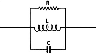
Fig. 2 - Equivalent circuit of a coupling loop.
The spacing between the loops can be determined, in terms of the mutual inductance,
from the following formula:2
M = 1.27ND
(6)
where M is the mutual inductance in micro-henrys, D is the diameter of the loops
in inches, and N is a factor depending on the diameter of the loops and the spacing
between the loops. Solving for N,
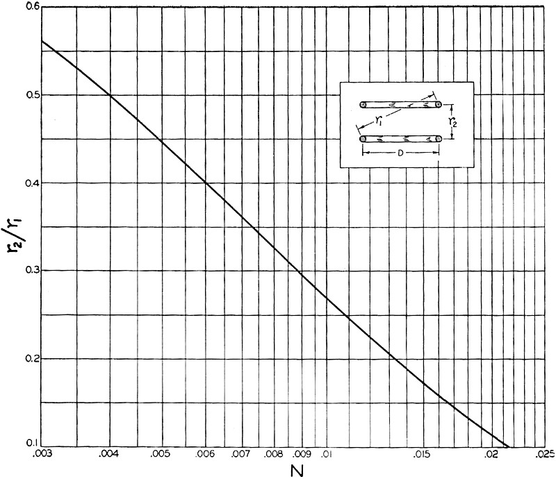
From Fig. 4 it will be noted that the value 0.00966 for N corresponds, with
sufficient accuracy for these calculations, to a ratio of 0.28 for r2/r1.
The diagram in Fig. 4 is a vertical section through the two coupling loops,
with r2 being the vertical distance or spacing between the loops and
r1 the diagonal distance from one side of the lower loop to the opposite
side of the upper loop. If Y is used to represent the ratio r2/r1,
then
Using the value 0.28 that has just been determined for Y, and 11 inches for the
diameter of the loops, D, the spacing between the loops, r2, can be found:
Construction and Tuning
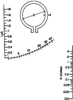
Fig. 3 - Nomogram for calculating dimensions of a single-turn
loop. To use, lay a straightedge through the desired inductance on the vertical
scale at the left and the conductor diameter on the vertical scale at the right.
The intersection of the straightedge with the curved scale gives the loop diameter
in inches.
All of the data are now available to make an efficient set of coupling loops
for 20 meters, when using a 300-ohm transmission line. The copper tubing should
be formed into as perfect a circle as possible, with the ends approximately one
inch apart. The variable condensers should be connected to the open ends of each
of the loops with as short leads as possible, because these leads are part of the
inductance. The condensers should be mounted in weatherproof containers that will
permit adjustment after the condensers are mounted. This can be accomplished by
slotting the condenser shaft and leaving a hole large enough for a screwdriver opposite
the end of the shaft. This hole can be covered with waterproof tape after each adjustment.
A simple weatherproof cover can be made by mounting the variable condenser on
a screw cap that fits a glass jar large enough to accommodate the condenser.3
The glass jar can be removed when adjusting the condenser, then replaced and sealed
with a rubber ring under the lid after the adjustments are completed. This type
of weatherproof covering can be mounted on the beam structure by fastening a bracket
to the lid. Regardless of the type of covering used, all steel parts should be painted
to prevent rust.
The writer's installation, using metal cans to cover the condensers, is shown
in one of the photographs. It will be noticed that a set of 10-meter coupling loops
is mounted coaxially with the 20-meter loops. Because of the difference in frequency,
these two sets of loops operate independently of each other.
Before installing the system in a transmission line, be sure that the antenna
has first been matched to the line. The tuning procedure consists of tuning the
secondary loop for maximum current in the transmission line to the antenna, and
tuning the primary loop to eliminate standing waves on the transmission line back
to the transmitter. If the spacing between the loops is correct, it will be possible
to adjust the condensers so that the s.w.r. on the line to the transmitter is minimum
at the same time that maximum current flows in the line to the antenna. This will
not be possible if the loops are too close together or too far apart.
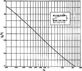
Fig. 4 - This graph is used in the determination of the
spacing between the primary and secondary.
The current indicator for the transmission line to the antenna is shown at I
in Fig. 1, and consists of a short length of transmission line with one end
shorted and a dial lamp connected across the other end. The length of this coupling
loop will depend on the current required for the lamp and the power delivered by
the transmitter. The indicator can be fastened to the transmission line with short
lengths of adhesive tape, and removed after the adjustments are made.
In tuning the primary loop for minimum standing waves on the transmission line,
a twin-lamp indicator, shown as SW in Fig. 1, is probably the easiest to use.
The only precaution that should be followed is to keep the twin-lamp at least three
feet away from the coupling loops. Also, if the section of transmission line on
which the twin-lamp is mounted is closer than 1/4 wave-length to the antenna, the
line should be perpendicular to the antenna. The primary and secondary loops both
may have to be tuned several times before the correct adjustment is achieved, since
any great change in capacity required to tune one loop will affect the tuning of
the other loop.
It might be well to point out that if the length of the driven element is not
such as to be resonant at the operating frequency, it may not be possible to match
the line to the antenna properly. When this is the case it may not be possible to
tune the loops correctly, because of the reflected reactance.
The transmission line may be matched to the antenna using any of the standard
methods. The delta match is too well known to require description here, but the
author believes that better use of the "T" match could be made if it is considered
as a folded dipole. It is doubtful if an impedance transformation greater than four
to one can be obtained with a "T" match using the same diameter conductor as the
radiator and spaced not more than four inches from it, regardless of how long it
is made. More satisfactory results can be had by using a smaller conductor for the
"T," and making it roughly 1/16 wavelength long. The match can then be achieved
by adjusting the spacing between the "T" and the radiator. The "T" match for the
radiator in my 20-meter three-element close-spaced beam is 10 feet long and uses
tubing 3/16 inch in diameter.
The spacing is 4 1/4 inches (center to center) from the radiator, which is 1
1/8 inches in diameter.
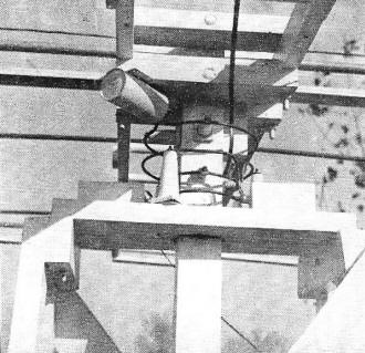
Mounting arrangement for the coupling loops. The upper set of
loops is for the 20-meter beam, the lower set for the 10-meter array. The tuning
condensers arc mounted in metal cans as described in the text.
Loops for other frequencies and other transmission-line impedances can be made
by using these same equations. If a Q of 5 is used for calculating a set of loops
for 10 meters the system will tune broadly enough to cover the entire 10-meter band
without serious standing waves appearing on the transmission line, providing the
antenna itself is flat over such a range. The higher the Q's of these loops, the
more sharply they will tune, and also the farther apart they will have to be spaced
to prevent overcoupling.
While the above calculations are based on the use of a balanced type of transmission
line, it should not make any difference whether the center of the loop is at ground
potential, as it is with a balanced transmission line, or whether one end of the
loop is at ground potential, as it is with a coaxial line.
With low-impedance lines a Q of 2 or 3 should be tried, in order to keep the
dimensions of the loops and the capacities of the condensers within reason. The
lower Q will require closer spacing, as the calculations will show.
Also, it is possible that a certain amount of impedance matching can be done
by connecting transmission lines of different characteristic impedance across the
primary and secondary loops, respectively, and calculating the spacing between the
loops on the basis of the resulting Q's. The difference in Q between the primary
and secondary loops will be taken into consideration when using equation (4).
As a matter of interest, the calculated values for loops of 1/4-inch tubing to
be used at various frequencies with various line impedances are listed in Table
I.
The W8ORI Dual Beam
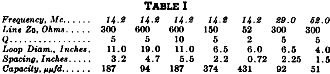
Table I - Calculated values for loops of 1/4-inch tubing to
be used at various frequencies with various line impedances.
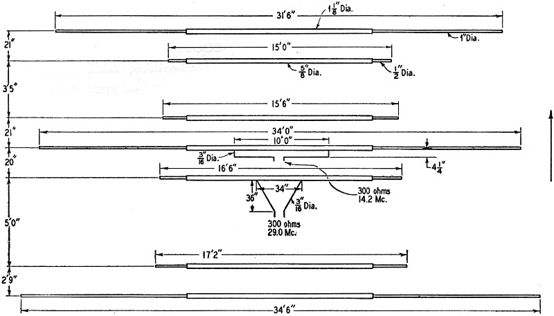
For those who may want the information, a sketch of the author's dual beam is
given in Fig. 5. There are three elements on 20 meters and four elements on
10, with all elements in the same plane. In both beams the reflector is 0.15 wavelength
from the driven element and the director is 0.1 wavelength from the driven element
(actually, the spacing for the 20-meter reflector is a little short). The parasitic-element
lengths were set by formula, while the driven elements were adjusted to obtain a
flat transmission line. It will be noticed that the 20-meter driven element is approximately
12 inches longer, and the 10-meter driven element 6 inches longer, than the lengths
given by the usual formula. This may result from the fact that the two driven elements
are located so close to each other, although the tuning of one has no appreciable
effect on the tuning of the other.
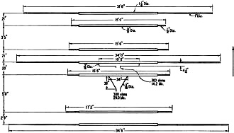
Fig. 5 - Dimensional layout of the W8ORI dual beam.
The 20-meter elements consist of a 12-foot section of aluminum tubing 1 1/8 inches
in diameter with a 12-foot section of 1-inch aluminum tubing telescoped into each
end. The 10-meter elements consist of a 12-foot section of brass tubing 5/8 inch
in diameter with a 3-foot section of 1/2-inch brass tubing telescoped into each
end.
The delta and "T" matching sections for the 10- and 20-meter beams, respectively,
are made of 3/16-inch copper tubing and extend toward the rear of the antenna. In
connection with the earlier remarks about "T" matching, it may be of interest to
mention that in the first attempt at matching the 20-meter beam the "T" section
was about 11 feet long and was spaced 3 inches (center to center) from the driven
element. The twin-lamp showed that the match was poor, regardless of adjustments
to the length of the "T'' section. The spacing was then changed and by experiment
it was found that a center-to-center spacing of 4 1/4 inches gave a good match.
The length of the "T'' was not at all critical, but the spacing was.
1 Taich, "Do It Inductively," Sept., 1947, QST; "Inductive Coupling to Rotary
Beams," Technical Topics, March, 1948, QST.
2 From "Radio Engineer's Handbook" by F. E. Terman, 1943. Courtesy of McGraw-Hill
Book Co.
3 This arrangement has been used by W8TDY.
Posted February 9, 2022
(updated from original post on 6/17/2016)
|