|
|||||||||||||
 |
|||||||||||||
An Inexpensive Impedance Bridge |
|||||||||||||
Here is an amazingly detailed article on how to construct and operate a near-lab-quality impedance bridge out of relatively inexpensive components. It appeared in a 1944 issue of QST magazine. A bridge is used to determine the precise value of a resistor, capacitor, or inductor. Prior to modern, easily affordable digital impedance meters, both amateurs and professionals relied on such devices for lab and field work. Why might you need to measure the value of a component when most are marked with a value? One common application is when a variable version of a component (or components) is soldered into the circuit while tweaking for optimal performance, and then the variable is replaced either with a single fixed component or a fixed component with a smaller-range variable component (the latter provides adjustment, but over a smaller range of values). It is not uncommon when doing the initial tuning on a complete home-built transceiver to have many variable components in place initially, and then solder in fixed versions later. This design centering process provides good reference values for future designs and makes the final product more affordable and compact, since variable are almost always more expensive and larger in physical size. An Inexpensive Impedance Bridge - The Principles and Construction of a Laboratory-Type Instrument for C, L and Measurements By Athan Cosmas* Many amateurs who have gone into advanced radio work, either in the armed forces or as civilians in industry, are becoming acquainted with the usefulness of laboratory-type precision measuring equipment. It is safe to say that the post-war ham will be far more "instrument-conscious" than he was in prewar days. He will consider an inexpensive but accurate Impedance bridge, such as the one described in these pages, an almost indispensable item of station equipment. Into the life of every ham there comes a time when the exact measurement of some value of C, L or R is required. It may be of a resistor which is to be used with a delicate relay, a coil for some type of filter, or perhaps a condenser which is needed in a special circuit. What to do? If there is no school laboratory handy, or if there are no friends who happen to own an expensive instrument such as the General Radio Type 650-A Impedance Bridge, the best "out" is to build an impedance bridge which will do the work. The bridge shown in the accompanying photographs will enable the making of all the measurements which usually are required in ham work. It has many of the fine features of the G-R bridge which it emulates. It will, of course, lack several of the fine points which contribute to the nicety and high accuracy of the expensive laboratory instrument i but it may be made from inexpensive parts, most of which the average ham has on hand, and it will have high enough accuracy for the average type of amateur measurements. The only hard-to-get item is the galvanometer.
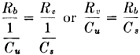
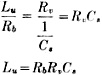
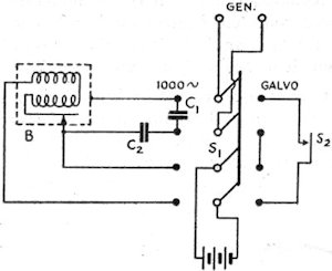
Panel view of the impedance bridge. The large dia in the center is the CRL dial, which controls R10. In the upper corners are the knob. for (left) the selector switch, S2, and (right) the multiplier switch, S1. In the bottom row from left to right are the Q dial controlling R12, the DQ dial controlling R11 and the D dial controlling R13. The generator or battery input terminals are located at the bottom, and the detector terminals at the top. The R terminals, to which unknown resistances are connected, are at the left, and the C-L terminals, to which unknown capacities or inductances are connected, are at the right. Photos &y Robert E. Cobaugh, W2DTE Range The complete circuit diagram of the instrument is given in Fig. 1. It includes a switching arrangement whereby any of the basic bridge circuits shown in Fig. 2 may be obtained. In Fig. 1, when selector switch S2 is in the position marked R, the circuit is that of the Wheatstone bridge, shown in Fig. 2-A. With this arrangement any resistance value from 0.01 ohm to 1 megohm can be measured when it is connected across the terminals at the right marked R. When the switch is turned to either of the positions marked CD or CDQ, the circuit is that of the capacity bridge shown in Fig. 2-B. Any capacity between 100 μfd. and 10 μμfd. connected across the C-L terminals can be measured with either of these arrangements. This circuit also provides for two ranges of power factor, 0 to 0.1 with S2 in the CD position and 0 to 1 with S2 in the CDQ position. With the switch thrown to the LDQ position, the circuit is that of the Maxwell bridge shown in Fig. 2-C. This circuit is used to measure the inductance of coils having values of Q up to 10. In the LQ position, the circuit is changed to that of the Hay inductance bridge shown in Fig. 2-D. With it, coils having values of Q up to 1000 can be measured. The inductance range is from 10 microhenries to 100 henries with either circuit. For the benefit of those who have not had occasion to work with bridge circuits of this sort R, in the past, a brief explanation of the operating principles will be given. Resistance Measurement Referring to Fig. 2-A, the fundamental bridge circuit consists of four resistance arms. Two of these arms, Ra and Rb, are made up of fixed resistance values which are selected by a dual tap switch, S1. The third arm, Rv consists of a calibrated variable resistor (in this case the resultant of R9 and R10 in parallel, because a variable unit of proper taper could not be obtained), while the fourth arm is composed of the unknown resistance, Ru.G is a d.c. galvanometer which, in effect, indicates the voltage differential between the midpoints of the upper and lower branches. The object in adjusting the bridge is to arrive at a balanced condition where no current flows through G. In order that no current shall flow through G, it is obvious that its terminals must be at the same voltage. For this to be true, the galvanometer must have each of its terminals connected at the same percentage of the total resistance in each arm. For instance, if Rb has three times the resistance of Ra, then the unknown resistance, Ru, must have three times the resistance of the variable resistor, Rv, when the latter is set for zero galvanometer current. Since Rv is calibrated, it is a simple matter to determine the value of the unknown resistance. From this reasoning we can set down the following proportion for the condition of zero current through the galvanometer: From this we obtain
Fig. 1 - Circuit diagram of the impedance bridge. C1 - 0.01μfd. mica (see text). C2 - 0.001μfd. mica. R1, R7 - 10,000 ohms, wire wound. R2, R6 - 1000 ohms, wire wound. R3 - 1 ohm, wire wound. R4 - 10 ohms, wire wound. R5 - 100 ohms, wire wound. R8 - 100,000 ohms, wire wound. R9 - 41,000 ohms, wire wound. R10 - 15,000-ohm, wire-wound potentiometer. R11 - 16,0000-ohm, wire-wound potentiometer. R12 -165-ohm, wire-wound potentiometer. R13 - 1600-ohm, wire-wound potentiometer. R14 - 70 ohms. (Note: Odd-size resistance values may be composed of two or more standard-value resistors in series.) S1 - Sections of 2-gang, 7-position rotary switch. S2 - Sections of 2-gang, 4-circuit, 5-position rotary switch (Centralab 2515). It is apparent that the unknown resistance, Ru, must always be equal to the value of resistance at which the variable resistor, Rv, is set, times a multiplying factor represented by the ratio Rb/Ra. lf some fixed value is selected for Ra, then a change in Rb alone will change the multiplying factor. Thus, the several resistances (R3, etc.) represented by Rb may be considered as multipliers for the range of Rv. As an illustration, in the instrument shown in the photographs Rv is 10,000 ohms, Ra is also 10,000 ohms (except for the highest resistance range, G in Fig. 1), while the tap switch, S1, changes Rb in steps of 10 to 1; i.e., 1 ohm, 10 ohms, 100 ohms, etc., up to 100,000 ohms. The multiplying factors which can be applied to the resistance setting of Rv are, therefore, or, in decimal equivalents, 0.0001, 0.001, 0.01, etc. Since the useful range of Rv is assumed to be from 100 to 10,000 ohms, the successive ranges of resistance measurements which can be made by the bridge are from 100 X 0.0001 = 0.01 ohm to 10,000 X 0.0001 = 1 ohm when Rb = 1 ohm; from 100 X 0.001 = 0.1 ohm to 10,000 X 0.001 = 10 ohms when Rb = 10 ohms; from 100 X 0.01 = 1 ohm to 10,000 X 0.01 = 100 ohms when Rb = 100 ohms etc. Therefore, with the particular values selected for this bridge, the maximum resistance measurable in each range is equal to the value of Rb selected by the tap switch, S1. In the wiring diagram of Fig. 1, R1 and R2 are the resistors represented by Ra, while R3 to R8 are the resistors represented by Rb. Rv represents the resultant of R9 and R10 in parallel. When S1 is turned to the last tap (G), Ra is changed from R1 (10,000 ohms) to R2 (1000 ohms). In this position, Rb (which represents R8) has a value of 100,000 ohms. The .multiplying factor for this range is, therefore, As Rv is varied from 100 to 10,000 ohms, the resistance-measuring range runs from 100 X 100 = 10,000 ohms to 10,000 X 100 = 1,000,000 ohms = 1 megohm. In use, the unknown resistance is connected to the terminals marked R, the CRL multiplier switch, S1, is turned to the approximate value and the CRL dial, controlling R10, is adjusted for zero galvanometer current, The CRL dial reading is taken and the multiplying factor indicated by the position of S1, as shown in Table I, is applied to the CRL dial reading to obtain the value of the unknown resistance. If the bridge is very far off balance when the battery voltage is applied, excessive current may flow through the galvanometer. While R14 serves to limit this current, a push-button switch may also be incorporated in series with the galvanometer so that the battery voltage may be applied only momentarily until the arms are adjusted for an approximate balance.
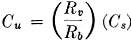
Fig. 2 - Basic bridge circuits. A - Wheatstone bridge used for resistance measurements. B - Capacity bridge for measuring capacity and power factor. C - Maxwell inductance bridge. D - Bay inductance bridge. Labels on components refer to similar components and labels in Fig. 1 and to designations in the text. The respective dials controlling each variable unit also are indicated. In A, a DeJur student galvanometer or its equivalent is suitable for G. The galvanometer is strictly necessary only for low-resistance measurements. The 1,000-cycle a.c. source and headphones may be used for measuring the higher resistance values as well as for inductance and capacity. Capacity Measurement When selector switch S2 is in the CD position, the circuit becomes that of the capacity bridge shown in Fig. 2-B. This arrangement is similar to the Wheatstone bridge circuit used for resistance measurements except that two of the arms contain capacities - one the unknown capacity, Cu, and opposite it a known capacity, Cs. The principle of obtaining a balance is much the same as that described for the Wheatstone bridge. In order to obtain voltage drops across the condensers, it is obvious that an a.c. source must be used instead of a battery. This is provided by a 1000-cycle generator. In place of the galvanometer a pair of headphones is used as an indicator, and the bridge is balanced when the arms are adjusted to give minimum response in the headphones. Since the impedance of a condenser is in inverse proportion to its capacity, the expression for a balance becomes From this we obtain From the above, we see that the ratio Rv/Rb is the multiplying
factor to be applied to the standard capacity to obtain the unknown value, Cu.
The highest capacity range is made available when Rb is set at one ohm.
The multiplying factor then becomes
Behind the panel of the impedance bridge. This view shows the multi-tap switches, the fixed standards and the four variable-resistance units. Power Factor When making capacity measurements with the bridge it will be found impossible to obtain a complete balance unless the power factor of the condenser under measurement happens to be the same as that of the standard condenser, because of the difference in phase shifts. A condenser with a power factor greater than zero may be represented by a pure capacity (a condenser without losses) in series with a resistance. Therefore, if the losses of the condenser used as a standard are negligible, the power factor of the arm containing the standard may be made the same as the power factor of the arm containing the unknown capacity by adding resistance (R11 or R13 in Fig. 2-B) until the circuit is in balance. The setting of the series resistance for balance thus serves as a means for measuring the power factor. A close approximation of the power factor of a condenser is given by the ratio
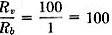
R/X, which is known as the dissipation factor. Here R is the equivalent series resistance
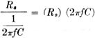
and X the reactance of the condenser. The latter is equal to
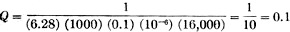
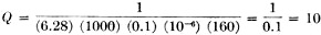
p.f. = As an example, we know that the frequency is 1000 cycles and the capacity 0.01 μd. = (0.01) (10-6) farads. Substituting these values, we obtain p.f. = (Rs) (6.28) (1000) (0.01) (10-6) = (Rs) (0.0000628) Rs represents either of the variable resistances, R11 or R13, in the standard arm in Fig. 2-B. R11 is in the circuit when S2 is in the CDQ position. It has a maximum resistance of 16,000 ohms and is controlled by the dial marked DQ. At full scale the power factor of the standard arm is (16,000) (0.0000628) = 1. When S2 is in the CD position the circuit is the same except that R13, with a maximum resistance of 1600 ohms, is substituted for R11. R13 is controlled by the dial marked D. When R13 is set at maximum the power factor indicated is 0.1. If the DQ dial is marked 0 to 10, its readings should be multiplied by 0.1 to obtain the correct power factor. (See Table III.) Similarly, the D dial reading should be multiplied by 0.01. In practice, S1 is first set to the appropriate range for the capacity to be measured. The CRL dial controlling R10 is then varied for minimum response in the headphones. Finally, the D or DQ dials and the CRL dial must be carefully juggled back and forth for minimum response. When the positions giving the lowest possible response are found, dial readings of capacity and power factor can be made.
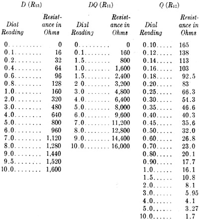
Table I This table shows the multiplying factors which must be applied to the readings of the dial calibrations given in Tables II and III. Depending upon the position of tile multiplier switch, S1 in Fig. 1, CRL dial readings should be multiplied by the factors shown below to give the correct values in the units indicated. When making p.f. measurements on the D dial, multiply the dial reading by 0.01. When making p.f. measurements on the DQ dial, multiply the dial reading by 0.1. When making Q measurements on the DQ dial, multiply the dial reading by 1. When making Q measurements on the Q dial, multiply the dial reading by 100.
Table II This table shows how the CRL dial controlling R10 should be marked to be direct reading for various resistance settings. For example, when the parallel combination of R9 and R10 in Fig. 2 is adjusted to a resistance of 1500 ohms, the CRL dial scale should be marked 1.5.
Table III This table shows how the D, DQ and Q dials should be marked to be direct reading for each resistance setting of R13, R11 and R12 (Fig. 2), respectively. Inductance Measurement When selector switch S2 is turned to the LDQ position, the circuit becomes that of the Maxwell inductance bridge shown in Fig. 2-C. The Hay inductance bridge of Fig. 2-D is obtained with S2 in the position marked LQ. The circuits are the same insofar as the measurement of inductance is concerned; they differ only in the ranges of Q which may be measured. Since the impedance of a coil is proportional to its inductance while that of a condenser is in inverse proportion to its capacity, the condition for balance in the circuits of Fig. 2-C and 2-D is given by From this we see that the product of RbRv is the factor by which the numerical value of Cs must be multiplied to obtain the value of the unknown inductance. Both inductance and capacity are expressed in units of similar order; i.e., in henries and farads. In the circuits of Figs. 2-C and 2-D, Cs represents C1, which has a capacity of 0.1 μfd., while Rv may be varied from 100 ohms to 10,000 ohms and Rb from 1 ohm to 100,000 ohms, as before. The smallest multiplying factor is obtained when Rv and Rb are at their minimums of 100 ohms and 1 ohm respectively. Then the factor becomes 100 and Lu = (100) (0.1) = 10 μh. (μh. because Cs is expressed in μfd.). The largest multiplying factor is obtained with the maximum values of resistance for both Rv and Rb, which are 10,000 ohms and 100,000 ohms, respectively. The factor at this end of the range is (10,000) (100,000) = 109 and Lu = (109) (0.1) = 108 μh. = 102 h. = 100 h. Therefore, the range of the instrument on inductance measurements is from 10 μh. to 100 h. As in the case of capacity measurements, it will be found necessary to balance resistive components as well as reactive components in the nonresistive arms. The amount of resistance which must be added in the capacitive arm to obtain minimum response in the headphones may be used as a measure of the Q (or X/R) of the coil. Since the reactance of the standard condenser, Cs is given by
When selector switch S2 in Fig. 1 is in the LDQ position for the Maxwell bridge circuit of Fig. 2-C, Cs = C1 = 0.1 μfd. and R = R11, which is the variable resistor controlled by the DQ dial and which has a useful range of 160 to 16,000 ohms. The frequency is, of course, 1000 cycles, as before. Substituting these values in the above equation,
(the factor 10-6 in the above denominator being necessary in converting to farads). At the other end of the range of R11,
Thus the range of this circuit in measuring Q is from 0.1 to 10. When S2 is in the LQ position to give the Hay bridge circuit of Fig. 2-D the procedure is the same, except that R12, which has a useful range of 16.5 to 165 ohms, is substituted for R11. This gives a range of Q from 10 to 1000. Constructing Resistance Standards Most of the constructional details may be observed from the photographs. If the case is made of sufficient size, the galvanometer, battery and 1000-cycle source can be included in the unit for greater convenience. The absolute accuracy of measurements made with the bridge naturally will depend upon the accuracy of the fixed resistors and condensers used as standards, as well as the calibration of the variable resistors. Ordinary copper magnet wire may be used in constructing homemade fixed resistance standards of values up to 10,000 ohms. Reference to the wire table in the Handbook (see pages 401 and 427 in the 1944 edition) will show the approximate resistance of copper wire of various sizes. For instance, the table shows that No. 28 wire has a resistance of 66.2 ohms per 1000 feet, or 0.0662 ohms per foot. Therefore, a length of about 16 feet will have a resistance of approximately 1 ohm.
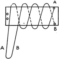
Fig. 3 - Method used for winding noninductive resistance standards from copper magnet wire. See text for details. The standard resistors (R1 through R8) must be of the noninductive type. Fig. 3 shows the method used in winding the lower-value resistors on a thin strip of Bakelite. The two ends of the wire first are soldered to the terminals at one end of the strip. The two half-lengths of wire are then wound in opposite directions around the Bakelite strip and the loop end fastened to the other end of the strip. This method was used in making the 1-, 10- and 100-ohm standards. For the 1000- and 10,000- ohm units half-inch Bakelite rod was used, grooves being cut in the rod so that the windings could be made in pies. Each pair of adjacent pies was wound in opposite directions. Resistance wire rated at 80 ohms per foot was used, wound 250 ohms per pie for the 1,000-ohm units and 2500 ohms per pie for the 10,000-ohm unit. Two 50,000-ohm meter multipliers, rated at 1 per cent accuracy, were connected in series to provide the 100,000-ohm standard. Calibration The most accurate means available should be used in checking the resistance of the standards. A local serviceman or a school laboratory may have a resistance bridge which can be borrowed to make the calibrations. The wire-wound units can be adjusted to exact values by removing the insulation from the loop end and twisting the loop until the correct value is obtained. An accurate calibration must also be obtained for the R9R10 combination. The curve should be checked at as many points over the range of R10 as possible. If a 10,000-ohm resistor with a logarithmic taper is available it may be used to replace the parallel combination. When building this unit a potentiometer of this type could not be obtained locally, and so the combination of R9 and R10 was used to obtain an approach to the desired logarithmic characteristic.
Fig. 4 - Circuit of tbe 1000-cycle tone source. C1 - 0.5 μfd. C2 - 0.1 μfd. S1 - 4-p.d.t. switch. S2 - Push-button switch. B - High-frequency buzzer. Once the fixed resistance standards and R10 are calibrated, it is a relatively simple matter to calibrate R11, R12 and R13 by simply connecting them to the R terminals of the bridge. These three units preferably should also have a logarithmic taper. Condensers having capacities as close as possible to..the required values of 0.1 μfd. and 0.01 μfd. should be used for the capacity standards. Both should be of the mica type, to minimize loss errors. C1 may be made up of a combination of smaller-capacity units in parallel, if necessary. The accompanying tables (II and III) show how the dials should be marked to be direct reading. Fig. 4 shows the circuit of an inexpensive generator suitable for the 1000-cycle signal source required for measuring capacity and inductance. The frequency can be checked with sufficient accuracy by matching it up with the second B above middle C on a correctly tuned piano. The buzzer should be enclosed in a sound-proof box.
Posted July 20, 2021 |
|||||||||||||
 |
|||||||||||||
|
|||||||||||||

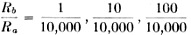 , etc.
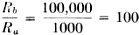

 when Rv = 100 ohms,
and
when Rv = 100 ohms,
and  = 10,000 when Rv = 10,000.
At the other end of the range, when Rb is set at 100,000 ohms the multiplying
factor is reduced to
= 10,000 when Rv = 10,000.
At the other end of the range, when Rb is set at 100,000 ohms the multiplying
factor is reduced to  = 0.001 when Rv = 100 ohms
and
= 0.001 when Rv = 100 ohms
and  = 0.1 when Rv = 10,000 ohms.
The standard represented by Cs is C2 in Fig. 1. It has
a value of 0.01 μfd., to which the above multiplying factors are applied when
determining the value of the unknown capacity. The total capacity range varies from
100 μfd. when
= 0.1 when Rv = 10,000 ohms.
The standard represented by Cs is C2 in Fig. 1. It has
a value of 0.01 μfd., to which the above multiplying factors are applied when
determining the value of the unknown capacity. The total capacity range varies from
100 μfd. when  = 10,000 to 0.00001 μfd. = 10 μμfd.
when
= 10,000 to 0.00001 μfd. = 10 μμfd.
when 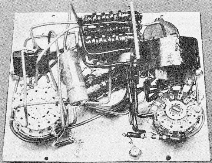
 where f is the frequency of the applied voltage
in cycles and C the capacity of the condenser in farads. Therefore, in Fig. 2-B,
where f is the frequency of the applied voltage
in cycles and C the capacity of the condenser in farads. Therefore, in Fig. 2-B,
 (Rs) (2


|
||||||||||||||||||||||||||||||||||||


