May 1941 QST
 Table
of Contents Table
of Contents
Wax nostalgic about and learn from the history of early electronics. See articles
from
QST, published December 1915 - present (visit ARRL
for info). All copyrights hereby acknowledged.
|
There is still a lot of vintage ham radio
equipment in use both by the original owners and by newcomers who buy the equipment
at Hamfests and on eBay. User's manuals are hard to come by, since they often were
separated from the original gear a long time ago. Knowing how to operate, repair,
and align everything properly is still necessary, especially as the airwaves get
ever more crowded and the FCC gets more serious about prosecuting violators. Old
editions of QST are the perfect resource for locating such information.
This article covers some of the basics of oscillators - tritet types in particular
- used for CW keying. The tritet oscillator gets is name from having been designed
originally to efficiently generate third and fourth harmonics, per James Lamb's
June 1933 QST article "A More Stable Crystal Oscillator of High Harmonic
Output." ARRL members can download the article
here. The Wikipedia
entry for the tri-tet oscillator mentions that radio raconteur and Ham radio operator
Jean Shepherd (of "A
Christmas Story" fame) referenced his own tritet circuits.
...and Some Observations on Blocked-Grid Amplifier Keying
By Byron Goodman WIJPE
Assistant Technical Editor, QST
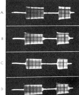
Fig. 1 - Some oscillograms of the keying of a grid. plate
oscillator (see Fig. 3). The oscillator is keyed in the negative lead, with
no key filter, so that the pure characteristic can be seen. A, B and C show a 6V6
grid. plate oscillator tuned for optimum keying, the high-frequency side and the
low-frequency side of optimum, respectively. D shows a 6L6 substituted for the 6V6
and tuned for optimum.
(The oscillograms on these pages all show the second dot shorter
than the first. This is caused by the 'scope sweep circuit not having a pure saw-tooth
form, something that is often encountered at low frequencies.)
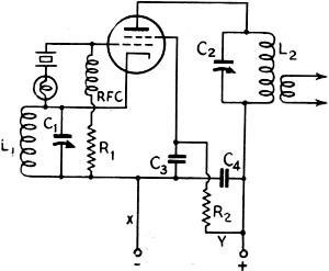
Fig. 2 - The Tri-tet oscillator. The value of C3
will introduce some lag and thus reduce clicks if a well-screened tube is used.
Negative high-voltage keying is done at "X", and screen-grid keying at "Y."
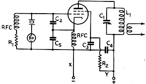
Fig. 3 - The grid-plate oscillator. The remarks about F.g.2
also apply to this type of oscillator. C2 should be 50 μμfd. and C5
will range from 50 to 250 μμfd., depending upon the tube. Some versions of this
circuit use only the input capacity of the tube for C2, but the addition
of the small condenser is worth trying.
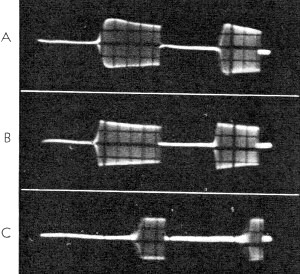
Fig. 4 - Oscillograms of a keyed 6C5 crystal oscillator.
A shows the triode adjusted for optimum keying with a 10,000-ohm grid leak, B shows
the triode with cathode bias and tuned for optimum keying, and C shows what happens
when the cathode- (or grid-) leak biased triode oscillator is tuned too much to
the low-frequency side of the optimum keying adjustment. The dots in C become light
and the keying is somewhat erratic.
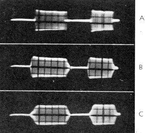
Fig. 5 - A 6AG7 leak-biased Tri-tet oscillator with the
plate tuned to the fundamental frequency. A shows the oscillator tuned for optimum
keying, and B shows the same with optimum key filter. Both A and B are keyed in
the negative lead; C is keyed in the cathode with the same filter as B. Adding capacity
to C did not extend the tail on "break" enough to reduce the click to a good value.
The subject of crystal oscillator keying is complicated somewhat by the differences
in various crystals, tubes and circuits. All crystals do not key alike, some circuits
are better than others, and different types of tubes in the same circuit behave
differently. For these reasons, it is well-nigh impossible to set down any hard
and fast rules about crystal keying that will apply in every case. However, work
in the laboratory with the more common tubes and circuits has resulted in some general
principles that can be applied to all crystal oscillators that are being adjusted
for keying.
"Adjusting an oscillator for keying" is nothing new to the experienced amateur
who uses several different crystals and has worked with the problem, but it may
come as a shock to those who work on the premise that a crystal oscillator adjusted
for maximum output need only be turned on and off rapidly with a key to affect good
keying. As with self-excited oscillator keying, the best procedure for adjustment
of a crystal oscillator seems to be first to adjust it so that it follows the key
closely at quite high speeds, and then to introduce some filter to reduce the clicks
to the degree necessary only for good communication at amateur code speeds. The
better crystal oscillator circuits are all capable of keying speeds up to well over
100 w.p.m., but a keying circuit capable of handling this speed cleanly results
in more key clicks than are necessary for the more normal speeds of from 20 to 35
w.p.m., and so some lag should be added.1
One slight disadvantage of crystal oscillator keying is that, when several crystals
are used (for different parts of the bands), the total current to the oscillator
is not the same in every case. This means that a key filter adjusted for one particular
voltage-current combination may introduce too little or too much lag on "make" and
too much or too little lag on "break" when a different crystal (with different total
oscillator current) is used. This is likely to be the case, since all crystals do
not key best with the same tuning adjustment. It is, however, a fine point that
is mentioned only to explain the apparent discrepancies some operators encounter.
As is the case with self-excited oscillators, cathode keying of a crystal oscillator
seems to be more difficult to filter than power-supply keying (in the negative or
positive lead). The time constant of the oscillator grid circuit has an effect on
the keying, and simply adding a lag circuit at the key is not as effective as might
be thought. The photographs in Figs. 5B and 5C show a comparison between the effectiveness
of key filters in the cathode and negative leads of a crystal oscillator. Cathode
keying has won popularity because, for the same oscillator, the sparking at the
key and the voltage across the key is less than with power-supply keying. The obvious
answer is, of course, to key a low-power circuit where these factors become unimportant.
Combination oscillators such as the Tri-tet (Fig. 2) and the grid-plate
oscillator (Fig. 3) that use the screen grid as the grounded anode in the oscillating
circuit can, when used with well-screened tubes, be keyed satisfactorily in the
screen circuit when doubling. If the plate voltage is too high or if the screening
is poor, the crystal will oscillate weakly all of the time and discourage break-in
work on one's own frequency but the circuit has the advantage that the screen dropping
resistor, R2, and the screen by-pass condenser, C3, serve
as a filter that helps to reduce clicks. When adjusting for minimum clicks, the
values of C3 and another condenser across the key should be varied until
the results are satisfactory. Well-screened tubes like the 6SK7, 6AG7 and the 10-watt
pentodes are satisfactory in this application, but results with the more common
beam tubes (6V6, 6L6) will be discouraging, since the crystal will oscillate continuously.
General Considerations
One sometimes sees crystal oscillator circuits with no r.f. choke in series with
the grid leak across the crystal, but the slight saving in expense hardly justifies
the improvement in performance that can be obtained by using the choke. Several
circuits that gave mediocre keying with no choke showed a marked improvement when
the choke was added. The same sort of improvement is obtained when the value of
the grid leak is increased to 0.25 megohm or so, but this value of grid leak cuts
down the output of the oscillator to a point where it is of little value. The use
of the r.f. choke (and also a large value of grid leak) removes some loading from
the crystal and leaves it freer to start oscillating. As "musts" for most crystal
oscillator circuits that are keyed, it is recommended that the grid r.f. choke be
included and the value of grid leak be made as high as possible consistent with
adequate output to drive the following stage or, in the case of a single-stage transmitter,
to give sufficient output without a compromise with good keying. The straight tuned-plate
triode oscillator is an exception, and it is best operated with cathode bias only.
Frankly, we are at a loss to explain why the cathode-biased triode works better
than one with leak bias while all of the other circuits are better with leak bias
but such seems to be the case, as Figs. 4A and 4B show.
Simply using an r.f. choke and a high value of grid leak is not enough to give
good keying, of course. A suitable choke and condenser filter circuit must be used
at the key, and the key should be used in the negative (or positive, if it's hard
to get at the negative) lead, as described in the keying article last month.1
The same principles apply to adjustment - more choke is used to remove the click
on "make" and more condenser is used to remove the click on "break." It appears
to be slightly more difficult to smooth out the keying of a crystal oscillator than
of a self-excited oscillator, possibly because one is dealing with a partially mechanical
oscillator instead of a purely electronic one, but in general it will respond to
the same treatment.
The oscillator should be capable of oscillating with only 3 or 4 volts on the
plate and an excellent test is to connect several dry cells in series for the plate
supply to check this point. An oscillator that won't oscillate at a low plate voltage
will drop in and out of oscillation with a "plop" as the voltage is increased from
zero and decreased back again, and hence is not as susceptible to key filtering
as one that will work at a low voltage. Straight pentode oscillators and some triode
oscillators will require additional feedback to make them oscillate at less than
10 or 15 volts. Under critical adjustment, the Tri-tet will oscillate with no apparent
plate voltage when the circuit is closed (as is well known), but this is caused
by the contact potential of the tube and the drop through the cathode circuit. The
grid-plate oscillator (Fig. 3) will oscillate at very low voltages with proper
proportioning of the cathode con-denser, C5.
Last month we presented a story pointing out some of the factors influencing
the keying of amplifiers and self-excited oscillators. This follow-up article treats
some of the considerations in crystal-oscillator keying and the blocked-grid keying
of amplifiers (and keyer tubes) and, although it may not offer the cure-all for
your particular problem, it may start you in the right direction towards clearing
up your keying troubles.
Another important factor in the adjustment of a crystal oscillator for best keying
is that it be keyed while tuned. Electronic bug owners will find this a simple matter,
while the straight key or mechanical bug owners will have to content themselves
with sending a series of dots while tuning the oscillator. It is relatively easy
to hit the best tuning adjustment by listening to the signal in the receiver, but
one can end up with some rather horrible keying if he just tunes the oscillator
for maximum output and then keys it. This is assuming, of course, that a proper
key filter has already been installed and that the switch to a different crystal
has just been made. The key filter constants can be determined in the same manner
as described last month for self-excited oscillators. Be sure to listen with the
r.f. gain of the receiver well reduced, else the receiver is likely to give too
pessimistic a picture of the clicks.
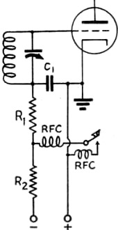
Fig. 6 - Grid-block keying circuit. R1, is the
normal grid leak and C1, is the r.f. bypass condenser plus enough capacity
to give a good keying characteristic. R2 is included to prevent a short
circuit of the blocking-voltage supply when the key is closed. Increasing the size
of C1, will make the keying "softer" on both "make" and "break;" making
R2 larger will soften "break."
If the oscillator circuit is one using a screen grid tube, the screen circuit
should not be overlooked when adjusting for minimum clicks. The size of the dropping
resistor is usually fixed by the screen operating voltage, but the size of the by-pass
condenser can increase or decrease the clicks, depending upon the type of circuit.
It is suggested that a 0.001 by-pass condenser be used right at the socket, for
a short r.f. path, and then different values of shunting condensers can be tried
at some more accessible point. Here again testing is most readily done by sending
a steady string of dots and listening to the signal (with the b.f.o. turned off)
while different values of screen by-pass condensers are tried. The screen adjustment
is best made before the key filter is adjusted. The additional capacity should be
added on the tube side of the dropping resistor, of course.
Loading has an effect on the keying of oscillators where the feedback is obtained
from the plate circuit, as in the case of the straight tetrode or triode oscillators,
but it doesn't seem to be very important in circuits like those shown in Figs. 2
and 3.
A conclusion from the work described in this article is that the regenerative
type of crystal oscillator (Tri-tet and grid-plate) keys better than the straight
triode, tetrode and pentode oscillators. Not only do they seem to work more uniformly
with different crystals, but their optimum keying is more likely to occur at the
maximum output point. It may very well be possible to make a triode or multi-element
tube oscillator show similar results by adding additional feedback from plate to
grid, but the Tri-tet and grid-plate oscillators are easier to control.
Grid-Block Keying
The use of a blocking voltage on the control (or suppressor) grid of a tube to
cut off its output until the blocking voltage is removed by the shorting of the
key, as shown in Fig. 6, is an excellent method of keying an amplifier. The
resistor R1 is the normal grid leak and R2 is a resistor used
to prevent the blocking-voltage supply from shorting when the key is down. The capacity
C1 is the normal r.f, by-pass plus any additional capacity necessary
for a good keying characteristic. A nice feature of grid-block keying is that it
requires no inductance to give a lag on "make," the lag coming from the time constant
of C1 discharging through R1. On "break," the constant is
determined by C1 charging through R1 plus R2. Since
the grid leak, R1, is determined by the tube .that is being keyed, adjustment
of a grid-block keying system consists of adding enough capacity across C1
until the" make" is as soft as desired and then, if the "break" still shows some
click, raising the value of R2 until desirable keying is obtained. The
same rule as set forth in the previous article applies - it is preferable to have
a harder "make" than "break" for good copy at high speeds, and this is obtained
automatically with grid-block keying. The same adjustment procedure applies to tube
keyers (that use a blocking voltage) and to suppressor-grid keying.
Grid-block keying is most convenient in amplifier stages using high-μ tubes that
aren't being driven too hard, since such stages will require a lower voltage for
cut-off.
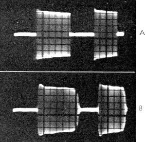
Fig. 7 - Grid block keying of an amplifier. A shows the
characteristic with only the normal grid leak and r.f. by-pass condenser, B shows
the addition of 0.1 μμfd. across the condenser. The clicks of B were very slight,
with almost none at all on "break." Note that the addition of capacity in B has
made the dots "heavier," requiring a slight readjustment of the key if a bug is
used.
Unfortunately, grid-block keying does not work any too well with oscillators.
It can be used, of course, but it isn't possible to get a soft "make" characteristic
because the bias must be brought down to a value that gives a high enough mutual
conductance before the tube will oscillate and it then plunges into oscillation
in the usual manner. Further, a soft "tail" is not added to the oscillator when
grid-block keying is used as is added to an amplifier keyed this way. The closest
approach is suppressor-grid keying of a Tri-tet or grid-plate oscillator, and these
both require that the oscillator run constantly, prohibiting break-in on one's own
frequency without elaborate shielding and neutralization.
Summary
In addition to the keying checks listed last month, the following applies specifically
to keyed crystal oscillators.
1. Holding the key down and tuning the crystal oscillator for maximum output
does not always give the optimum keying adjustment. Send a string of dots and tune
the oscillator for best keying.
2. A crystal oscillator should be capable of oscillating with only 3 or 4 volts
on the plate if it is to key well.
3. In adjusting the lag filter at the key, don't overlook the effect of the value
of screen bypass condenser if the oscillator is one that depends upon the screen
for feedback (Tri-tet or grid-plate oscillator doubling or with well-screened tube).
4. Use an r.f. choke in series with the grid leak and as high a value of leak
as is consistent with adequate output.
5. Don't be surprised if some crystals key better than others in the same circuit.
1 Goodman, "Some Thoughts on Keying," QST, April, 1941.
Posted April 2, 2021
(updated from original post on 8/9/2011)
|