|
July 1953 QST
 Table of Contents Table of Contents
Wax nostalgic about and learn from the history of early electronics. See articles
from
QST, published December 1915 - present (visit ARRL
for info). All copyrights hereby acknowledged.
|

The photo below of modulation types brought
to mind this classic image of
Calvin when he
was forced to get a haircut for school pictures day.
Author Howard Wright takes the opportunity here in a 1936 issue of QST
magazine to distill the concept of modulation down to its basic operation while
dispensing with the garbled mix of "graphs, formulas, charts, vectors, diagrams,
and Greek letters which often enter into various discussions of modulation." Mr. Wright
describes how to the uninitiated radio dial spinner, the culmination of events occurring
behind the scenes in an AM reception process is akin to this: "...it might be compared
to the reproduction of a color photograph in a magazine. How would we ever know
that, to be reproduced, the picture was broken down into its primary colors, if
all we had to go by was the original print and the magazine?" That is a very apt
comparison.
Low-Pressure Modulation Facts
Down-to-Earth Talk About Radiotelephony
By Howard Wright,* W1PNB
Several years ago, having built and operated several successful amateur radiotelephone
transmitters, I was reasonably satisfied with my knowledge of 'phone principles.
After all, they didn't seem too complicated, if one could manage to ignore the inconsistencies
that showed up now and then. To the best of my memory, I used to consider modulation
from about the following point of view:

"Sidebands a condition somewhat resembling a case of measles."
"The r.f. section of a transmitter consists of a carrier-generating exciter and
a final amplifier that amplifies the carrier and passes it along to the antenna.
To use this typical c.w. transmitter for 'phone operation, we merely couple voice
power to the final amplifier through a modulation transformer. The voice power is
then in series with the power supply to the final. Therefore, the level of the carrier
is varied above and below its original value at an audio rate. This is called 'modulating'
the carrier and is done to allow the voice signal to be recovered by a receiver."
As I said before, I was quite happy with the above understanding of a 'phone
transmitter. I suspect that there are many amateurs who are getting along nicely
today on similar ideas.
And then came single sideband! Formerly, I had considered sidebands as a condition
somewhat resembling a case of measles, occurring only on unhappily adjusted transmitters.
With the introduction of amateur s.s.b. techniques, we were informed that sidebands
are completely normal and honorable properties of all stations. Concerning modulation,
as the saying goes, "I didn't know from nothing."
At this point you may suspect that I have become one of those incurable single-sideband
enthusiasts. To this thought I happily plead guilty, but don't leave. I'll try to
keep the propaganda to a minimum.
This subject of modulation has been well covered in many excellent articles in
the past few years. If it hadn't, I would never be here with pen in hand. I am not
covering any new ground, but trying to present the material in a form that may be
helpful to those who are not on the best of terms with the graphs, formulas, charts,
vectors, diagrams, and Greek letters which often enter into various discussions
of modulation.
In my estimation there are two main reasons for the lack of a better general
understanding of 'phone principles. The first is that, in the hands of a person
without much theoretical knowledge, even the best of receivers tends to create a
false impression of the true nature of incoming signals. I will cover this more
thoroughly at a later time. The second reason seems to be our inability to connect
the modulation of a transmitter with the heterodyne process. But there I go, taking
for granted that everyone knows what the heterodyne process is. Let's back up several
steps.
The Language
At some point in our conversion from broadcast listeners to radio amateurs, we
discover a complicated electronic jargon. To most of us, this amounts to a new language
that must be learned if we are not to be baffled by the simplest of statements.
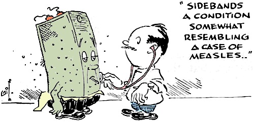
Among the new terms that tend to add most to the confusion of a beginner are: beat,
heterodyne, convert, mix and modulate. The fact that most of us never recognize
is that all of these imposing terms mean exactly the same thing. The different words
are only used as a matter of convenience, in indicating some general type of circuit.
Now it's not my purpose to try to explain why the heterodyne process works. To
put it briefly, however, here is how it works. Combine any two a.c. signals (regardless
of frequency) in a suitable circuit and two new signals will appear that are the
sum and difference of the originals. Probably most of us are familiar enough with
the operation of modern receivers to let us stop at this definition of the heterodyne
process.
At this point, it may seem that I have strayed quite a way from the subject of
modulating a final amplifier. Not so! The term "modulate" is included in the interchangeable
group of words that includes "mix" and "convert" - necessary processes in your receiver's
operation. I hope it is obvious that I am trying to point out that the action of
the little converter tube in your receiver is exactly the same as the process taking
place in your final during modulation. Of course, there are vast differences of
amplitude and frequency in these circuits. Nevertheless, if you can see their basic
similarity and actually start thinking of modulation in terms of converting, mixing,
heterodyning, beating, or whatever you want to call it, you have nearly won the
battle of understanding 'phone principles.
The Receiver
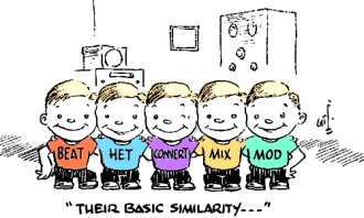
"Their basic similarity..."
Think of that pair of tubes in the final of your 'phone transmitter as a mixer.
I'll give more details later, but now back to the subject of deceiving receivers.
Before you rise to the defense of your particular high-priced beauty, let me
hurry to state that receivers only tell lies to people who don't realize that a
receiver, designed for broadcast-band type reception, inherently disguises the true
nature of incoming signals. Here is a typical example:
A neophyte tunes his receiver across an unmodulated carrier. The receiver tells
him that the carrier is a certain number of kilocycles wide. The neophyte immediately
starts a frantic and futile investigation to discover why one carrier is broader
than another.
Now let's have a man who has studied receivers tune the same receiver across
the same carrier. He also sees that the carrier occupies space on the dial but,
knowing that a carrier has no width, he realizes that the carrier is telling him
the selectivity, or "bandwidth," of the receiver.
This case of the unmodulated carrier is bad enough, but the receiver is designed
to perform a masterpiece of deception in the case of a modulated 'phone signal.
It does a perfect job of gathering in the various parts of the signal, eliminating
any evidence of the presence of the sidebands theory tells us were transmitted,
and combining the sidebands with the carrier in such a way that it appears that
the voice is simply superimposed upon the space supposedly occupied by the carrier.
So complete is this deception, that it might be compared to the reproduction of
a color photograph in a magazine. How would we ever know that, to be reproduced,
the picture was broken down into its primary colors, if all we had to go by was
the original print and the magazine?
Spectrum Space

"I can't quite give you a T9, OM."
Before we finish this business of generating sidebands, there is one very important
concept to grasp. No intelligence (modulation) can be transmitted without taking
up room in the spectrum. Couple this statement to the previously mentioned fact
that a carrier occupies no space and there is only one conclusion to be drawn. The
modulation can in no way be" on the carrier." It must consist of appropriate new
signals at frequencies "alongside the carrier." If we recall what has been said
about heterodyning signals, it takes no genius to see that the voice power from
the audio system of a transmitter, when applied to the final amplifier (or mixer)
doesn't affect the carrier in any way. It can't. Following the theory of mixing,
it combines with the carrier frequency to generate new r.f. signals, both above
and below the carrier, which can certainly be considered as riding" alongside the
carrier."
Now is the point where drawing a cute little diagram of carrier and sidebands
appears attractive, but let's proceed with just words.
Take the case of an ordinary amateur 'phone transmitter. For the sake of discussion,
let's say that the carrier frequency is adjusted to exactly 3900 kc. Now this happens
to be a fine transmitter, except for one fact. There isn't enough filtering in the
audio power supply, Of course, the result is a signal plagued with 120-cycle hum
or, in the words of c.w., "I can't quite give you a T9, OM."
Constantly remembering all we know about mixing, let's take a theoretical look
at our hum-modulated signal. The hum voltage of 120 cycles should mix with the 3900-kc.
carrier and produce new signals of 3900.120 and 3899.880 kc. In other words, we
should now have three separate signals, the strongest being the original, flanked
on either side by a "hum side-frequency" 120 cycles away.
Until now, references to receivers may not have seemed too flattering. This,
however, had only to do with the listener's lack of ability to interpret what he
heard. Now, let's use our receiver to tie down theoretical reasoning to what we
actually hear. Simply turn on the receiver's b.f.o. and tune carefully across the
hum-modulated signal. Presto! We hear three distinct points of "zero beat." We have
three signals. We have exact confirmation of the heterodyne theory of modulation.
If you're somewhat confused by my use of hum voltage in the above example, don't
be. It was simply used in place of "a single audio tone," which is often used in
explanations of sideband generation. Of course, hum is a far cry from the actual
voice signals we use to modulate our transmitters, but the heterodyne principle
remains unchanged, regardless of the type or complexity of the modulating signal.
The voice contains a great number of individual frequencies which beat with the
carrier. Each resulting new r.f. signal generated still maintains its original audio-frequency
relationship with each of its neighbors, even though the whole business has been
shifted up into the r.f. part of the spectrum.
Due to the heterodyne action, our complete band of audio frequencies is reproduced,
not only once, but in exact duplicate on either side of the carrier. Thus we have
the sidebands that have been discussed so much in recent years. Considering the
original audio frequencies, we might think of the sidebands as being "back-to-back."
The lowest-pitched sounds are close together alongside the carrier and the higher
ones, progressively removed from each other, cause the complete signal to be twice
as wide as the highest tone transmitted.
That's about the story of conventional a.m. If propagation conditions are good
and no mishaps (such as interference) befall this complicated group of signals,
we are all set to have the receiver perform its magic and restore human-sounding
values to the finished product.
S. S. B. Techniques
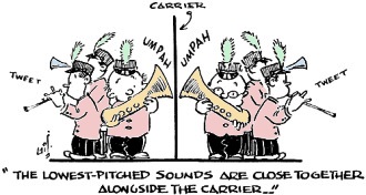
"The lowest-pitched sounds are closer together alongside the
carrier..."
Now, let's take a look at single-sideband techniques, which have almost completely
taken over transoceanic telephone service and are enjoying ever-increasing popularity
with radio amateurs. This definitely is not a drop-off point into the mysteries
of complicated electronics. If you once manage to grasp a firm understanding of
the regular double-sideband signals we have been discussing, single sideband is
only a small step away. After all, if we understand the whole of any subject, the
study of one of its parts shouldn't be too difficult!
Rather than start directly with s.s.b. transmitters, let's return to the though
of converting in a regular receiver. From one point of view, every superhet is a
s.s.b. receiver in two respects. The first, one which seldom needs to be considered,
is this: In converting incoming signals down to the intermediate frequency, the
new frequency (or sideband) caused by the difference between the incoming signal
and oscillator is the one that is used. The theory of heterodyning tells us that
the sum of these frequencies is also present at the output of the converter. This
sum frequency is so far removed from the i.f. that it is eliminated by the filtering
action of following stages.
The more important reason for considering a receiver as having s.s.b. action
concerns "image" reduction. Due to the heterodyne process, if no selectivity precedes
the converter, the receiver is sensitive to two frequencies. One is above and the
other below the oscillator by an amount equal to the i.f. I believe that most of
us are familiar with the drawbacks of having bad r.f. "images" or, in other words,
having each signal appear at two points on the tuning dial.
Here is the connection between receiver images and s.s.b. transmitters. The act
of adding r.f. selectivity to the front end of a receiver to reduce the image is
exactly the same process, in reverse, as adding a selective filter to a double-sideband
transmitter to reduce the" image sideband." The only difference is that the receiver
is purposely designed so that the image can be reduced by the use of a few simple
tuned circuits preceding the converter. In a transmitter, the sidebands produced
by modulation (conversion in a receiver) are separated only by a relatively few
cycles and are therefore more difficult to divide by filtering methods.
Until recent years, equipment selective enough to separate and suppress one sideband
was either nonexistent or very complicated. No doubt the basic advantages of transmitting
only one sideband were realized as early as those of having image rejection in a
receiver. However, in the case of the transmitter, the power in both sidebands was
recoverable by the receiver, plenty of space was available in the spectrum, and
no simple and effective way was available to eliminate one of the sidebands. Thus,
we have the predominance of a.m. as we know it.
You may have noticed that I have not stressed the "suppressed carrier" part of
s.s.b. There is enough material contained in this subject to fill a book, but it
is distinctly a separate subject from "single sideband." A very large part of both
the superiority of s.s.b. systems and the furor caused by the appearance of s.s.b.
signals on receivers tuned for regular operation can be attributed directly to carrier
suppression and not to the elimination of one sideband. This, however, is an article
on modulation, so let's stick to the sidebands.
Now, if we had to give a definition of single sideband, we could call it the
suppression of an "image sideband" for the purpose of reducing to a minimum the
frequency band necessary to transmit a given amount of intelligence. Because the
filter method is used for reducing the unwanted sideband or "image" in a receiver,
we will first consider this method as applying to transmitters.
Filters
A carrier is modulated in the ordinary way, producing identical sidebands on
either side of the carrier. These sidebands arid the carrier are fed into a very
sharp filter which passes one sideband and suppresses the other even though they
are very close together. There are LC filters, crystal filters, and mechanical filters.
They can all be built to do a good job of separating sidebands, but all have the
common property of having better selectivity as their design frequency is made lower.
This is the reason why practically all filter-type single-sideband transmitters
use receiver-type heterodyne methods to convert to the desired band from the lower
frequency at which the filter works well.
Phasing
The "phasing" method of s.s.b. generation employs theories which certainly seem
to belong to people with engineering degrees. However, the theory of filtering is
also basically very complicated, but we have been using different types of filters
so long that we tend to leave their mystic properties to the experts. Let's describe
the phasing system in terms similar to those used for filtering.
Each sideband is broken up into two parts by the use of a few craftily chosen
resistors and condensers, a couple of tuned circuits, and a certain amount of adjustment.
These parts of each sideband differ from each other only in that the times when
any given thing happens are different ("phase shift" to an expert). The four signals
thus produced are combined in another tuned circuit so that the parts of one sideband
"beat each other's brains out." The parts of the other sideband take an immediate
liking to each other and combine to form the signal intelligence to be transmitted.
The phasing method is not limited to low frequencies. It works as well at 50
Mc. as at 50 kc. However, for reasons of operating convenience, the signal is often
generated at some point outside the band and heterodyned in.
Before I finish, let me say that the previously mentioned s.s.b. properties of
receivers should, in no way, be confused with the general meaning of the term, "selectable-sideband
receiver." Such a receiver is actually able to remove the "audio image" from any
incoming signal. In plain words, it listens to either sideband and rejects the other.
Either phasing or filter methods are used in selectable-sideband reception. In fact,
the very parts used in a transmitter can almost always be used in a receiver.
In conclusion, if the above discussion of modulation differs so widely from your
ideas on the subject that you tend to become discouraged, remember that not knowing
all of the "lowdown" on such matters can't stop us in getting a lot of pleasure
from amateur radio. However, there isn't any doubt that the mechanics of radio communications
are becoming more complicated every day.
If we are to have any chance of keeping up with technical developments, the one
thing we can't afford to overlook is this business of mixing - sorry, I meant" modulation!"
Posted November 28, 2022
(updated from original post on (4/16/2016)
|