|
July 1953 QST
 Table of Contents Table of Contents
Wax nostalgic about and learn from the history of early electronics. See articles
from
QST, published December 1915 - present (visit ARRL
for info). All copyrights hereby acknowledged.
|
This is Part II of a 3-part series of articles
on magnetostriction devices. At audio and low IF frequencies, the use of ferrite
elements to construct relatively high-Q resonant circuits for filtering was a big
deal in the middle of the last century. Although not presented in this article,
design formulas and tables were published to implement the familiar Butterworth,
constant-k, Chebyshev, Gaussian, and other types. Tuning, particularly for higher
order filters, could be a chore since it involved a cut--and-try method on the ferrite
rods. However, that is what was available in the day, and it evidently worked well
enough to be worth the trouble for desired selectivity.
Magnetostriction Devices and Mechanical Filters for Radio Frequencies
Part II† - Filter Applications (see
Part I)
By Walter Van B. Roberts,* W2CHO
In the second part of this article, some applications of mechanical resonators
are discussed and a general description is given of a mechanical filter suitable
for intermediate frequencies.
Some Uses for Single Mechanical Resonators

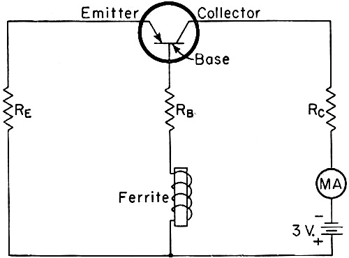
Fig. 13 - Ferrite oscillator using point-contact transistor.
Values should be adjustable for best results, although RC, used to limit
the collector current, can be a fixed resistor of 500 ohms. RB (1000-ohm
variable suggested) will not be needed with a good ferrite and transistor. BE
should he approximately 5000 ohms. Two good ferrite shapes are torsion cylinders
and concentric-shear disks. As an example of such a disk, a frequency of 273 kc.
was obtained with a disk of 25.4 mm. outer diameter and 9.5 mm. inner diameter.
The disk is put over the end of a short ferrite core that fills most of the hole,
and the coil goes over the middle of the core. Coil inductance is not critical but
too much inductance may start electrical oscillations. MA is a low-range milliammeter
(current about 0.5 ma.)
The use of a ferrite resonator as a high-Q tank circuit for an oscillator was
discussed in the preceding article. An oscillator using a transistor instead of
a tube, and requiring only two or three flashlight cells at negligible current drain,
makes a compact portable source of known-frequency oscillations of a few hundred
kilocycles or less. The frequency decreases less than 0.002 per cent per degree
Fahrenheit increase of temperature. A circuit is shown in Fig. 13. Harmonics
useful for checking receiver calibration can be heard, at least to 30 Mc., by directly
connecting the emitter to the receiver antenna terminal (single-wire connection
only).
It has been noted that the association of a ferrite resonator with a coil has
the same effect as inserting, in series with the coil, a high-Q parallel-tuned circuit.
The impedance of this circuit at resonance is k2Q times the coil reactance,
where k is the coefficient of coupling between the coil and the resonator and Q
is the mechanical Q of the resonator. Thus if, for example, k = 0.05 and Q = 2000,
the resonator effectively inserts in the coil a resistance five times as great as
its own reactance. Even if k is very small, a noticeable effect is produced. One
application of this effect is illustrated in Fig. 14, which shows an i.f. transformer
in a receiver equipped with a Magic Eye tuning indicator. A small ferrite ring,
permanently biased as previously described, is slipped over the lead to a coil,
and tuned to resonate in the radial mode at the center of the i.f. passband. The
coupling to the entire tuned circuit is very small because the main part of the
coil is not associated with the ring at all, but at resonance the ring inserts about
one ohm in series with the coil and this is enough to cause a flick in the Magic
Eye, and thus indicate correct tuning. Such an indicator would be useful in a high-fidelity
receiver where the shadow of the eye does not change noticeably over a considerable
range of tuning.
Perhaps the simplest use of a single ferrite resonator in a filter is to substitute
the resonator for the middle circuit of a three-circuit filter, as shown in Fig. 15.
The only difficulty here is the necessity for eliminating any appreciable direct
coupling between coils by way of the ferrite resonator, which acts as a core common
to the two coils. This is done by using a resonator several half waves long and
putting a copper tube over the middle part, as shown by the dotted lines. This tube
is grounded to ordinary shielding between circuits. The longer the tube and the
smaller its diameter, the more effective it is, but it is made very long the filter
band will have to be narrow. This is because the bandwidth varies with the coefficients
of coupling between the resonator and the tuned circuits and these coefficients
vary inversely with the square root of the number of half waves in the resonator.
For example, if a coefficient of 6 per cent is available between a half-wave resonator
and its coil, then if we use a four-half-waves-long resonator with a coil on only
the end half wave, the coupling between the coil and whole resonator will be only
3 per cent and the bandwidth about 4.2 per cent. The band could easily be made as
small as desired by using a very long resonator or by coupling the coils more loosely
to its ends, except for the fact that the Q of the coils must be approximately equal
to the reciprocal of the bandwidth expressed as a fraction, and this puts a lower
limit to bandwidth. For example, if the best Q available is 200, then the narrowest
band obtainable will be about 1/2 per cent. Fortunately, the range of about 1/2
to 4 per cent bandwidth is sufficient for many purposes.

Fig. 14 - Ferrite magnetostrictive ring used as a resonance
indicator in an i.f. amplifier.
The theoretical relations between bandwidth. coefficients of coupling, and coil
Qs to produce a desired transmission characteristic will be taken up later, but
in practice a filter of the sort shown in Fig. 15 can most easily be tuned
up by cut-and-try, the couplings, tunings and Qs being varied until a satisfactory
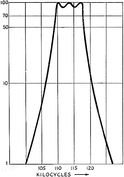
filter curve is obtained. As an example, Fig. 16 shows the measured curve of
output voltage of a filter employing a torsion ferrite 1/4 inch in diameter and
three half waves long, and adjusted to give a 1.3 db. peak-to-valley ratio.
Another way to eliminate direct coupling between the circuits of a filter using
a single ferrite resonator is to buck it out by means of an equal but opposite mutual
inductance. This method permits using resonators which are not adapted to the shielding
described above. As an example, Fig. 17 shows a ferrite ring resonator and
a bucking mutual inductance M which call be adjusted by moving a core or by varying
the separation between coils. In this figure R represents a radial-type ferrite
resonator, and as it is not practical to wind many turns on such a torus, a few
turns only are used in a link circuit coupled to the tuned circuit by a core C which
is preferably composed of a nonmagnetostrictive ferrite that gives the coils a high
Q. When M is adjusted for accurate balance, the performance is similar to that of
Fig. 16, but by a slight unbalance the cut-off can be made steeper on one side
of the passband or the other.

Fig. 15 - Simple filter using a magnetostrictive ferrite rod.
Dashed lines indicate how a copper tube may he slipped over the rod to reduce coupling
between the coils at the ends.

Fig. 16 - Measured resonance curve of a filter constructed
as in Fig. 15.
It is possible to use another resonator, tuned to a different frequency, to act
as the bucking mutual and thus obtain a lattice filter with four-circuit performance.
In fact, it is easy to construct a lattice filter with any number of resonators,
but in practice the adjustments of such a filter are so complicated that for more
than one resonator it is better to use the cascade type of filter to be described
later.
Before leaving the subject of filters employing a single ferrite resonator, one
more might be mentioned because it provides rejection points on each side of the
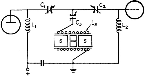
passband. Fig. 18 shows the arrangement used in an experimental circuit giving
nearly flat response over a band of 6.8 kc. at 455 kc., with rejection points 13.6
kc. apart and about 40 db. down.
In this filter a permanently-magnetized ring of ferrite is used in the torsional
mode, its axial length being ground to resonate at 455 kc. This is placed inside
a close-fitting coil form on which L3 is wound, and is flanked by slugs
S of inert ferrite which increase the coupling between the resonator and coil L3.
By reference to the equivalent circuit of Fig. 5 it can be seen that this is
a filter of the "m-derived" type. It can be systematically tuned as follows: with
C1 and C2 detuned, there is a sharp response at the frequency
of the ferrite. With the input set to this frequency, a jumper is connected between
the junction of the three condensers and ground, then circuits C1L1
and C2L2 are peaked up. (They tune substantially independently
since they are coupled only by the small inductance of the jumper.) Next, the jumper
is removed and C3 adjusted until the rejection points are properly located
on either side of the passband. The spacing between rejection points, as a fraction
of the midband frequency, is the same as the coefficient of coupling (k) between
the resonator and L3. The bandwidth is

again as a fraction of midband frequency. Thus, if all three coils are alike,
the band is 0.82 k. Note that the ratio of spacing between rejection points to spacing
between cut-off frequencies depends only on the inductances. Flatness of transmission
in the passband is obtained by adjusting the Qs of coils L1 and L2.
The Q of coil L3, however, should be made as high as possible by using
large-size Litz wire.
The Use of Ferrites in Multielement Filters

Fig. 17 - Filter using a toroidal ferrite magnetostriction
resonator, with separate mutual inductance for backing out coupling he tween input
and output coils.
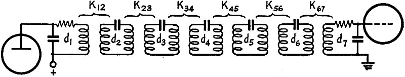
The simplest sort of multielement electrical filter is a chain of coupled circuits
as shown in Fig. 19, all circuits being tuned alike.
In this figure the ks represent the coefficients of coupling between adjacent
circuits, and as explained before, the coefficient of coupling between any pair
of circuits is equal to the fractional difference in frequency between the two response
peaks that would be observed if the same two like-tuned, high-Q circuits were used
as a two-circuit filter, like an ordinary double-tuned i.f. transformer. In other
words, if we want to make k23 = 0.03, for example, we would remove circuits
2 and 3 and use them as an i.f. transformer, increasing the coupling until the transmission
shows twin peaks separated by 0.03 fractional (or 3 per cent) in frequency. The
ds represent the dampings of the circuits, and in what follows, d is defined as
1/Q for each circuit.
Now, any combination of ks and ds will result in some sort of frequency selective
transmission or filter characteristic, but the ks and ds must be chosen in accordance
with appropriate equations to produce particular types of filters. Let us start
by supposing that the dampings are so small as to be negligible, except those of
the end circuits. Also let the desired fractional bandwidth be B. Then if we make
the first and last coefficients of coupling each 0.707B and the other couplings
each 0.5B while the damping of each end circuit is made equal to B, the result is
what may be called a simple Campbell filter. The only trouble with this filter is
that it has "ripples" toward the edges of the passband, although the transmission
is quite flat around midband. However, if there are not too many circuits in the
filter, the ripples near the edges of the band can be reduced, at the cost of introducing
some ripple at midband, by reducing the dampings somewhat from the value given above.
Very satisfactory characteristics can be obtained in this manner up to 5 or 6 circuits,
but as the number of circuits is increased, the ripple gets worse.

Fig. 18 - Filter with two rejection points, corresponding to m-derived type,
employing a ferrite ring magnetostriction resonator. The latter, shown in cross-section,
is mounted inside the form on which L3 is wound and is flanked by nonmagnetostrictive
slugs (S) to increase the coupling.

Fig. 19 - Multielement filter consisting of a chain of coupled circuits
tuned to the same frequency.

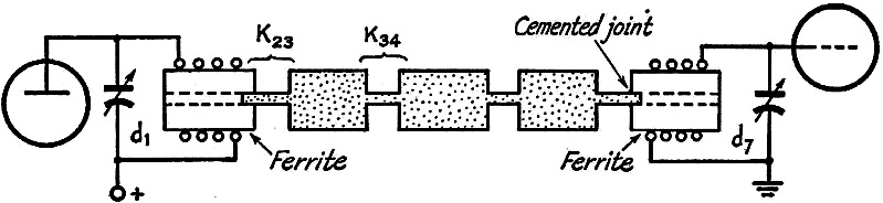
Fig. 20 - Mechanical filter analogous to the electrical
circuit of Fig. 19. High-Q mechanical resonators replace the three center circuits
of that figure, while the end sections are magnetostrictively coupled to the electrical
circuits.
In another type of filter called the Tchybescheff, the ks and ds are so chosen
that ripples occur all through the passband, but the peaks are all equal and the
valleys are all equal and the peak-to-valley ratio can be made as small as desired
by suitable choice of the ks and ds. It might well be asked why then not design
the filter for zero ripple? This, in fact, is easily done, and formulas for doing
so are given by Dishal1 both for filters with coupling and damping values
symmetrical about the center of the chain of circuits, and for filters with damping
at one end only. However, such "maximally flat" filters do not cut off nearly so
sharply outside the band as do filters which have a little ripple in the band. There
is a very great improvement in cut-off when even the slightest trace of ripple is
permitted, so that for any ordinary purposes it is desirable to design for the maximum
amount of ripple that can be tolerated. The calculation of the ks and ds to give
any chosen amount of ripple with any desired number of circuits can be carried out
as described in an earlier Dishal article.2
The foregoing circuit theory can now be transferred without alteration to mechanical
filters by substituting ferrite resonators for the next-to-end circuits and metal
resonators for the circuits in between. The couplings between end circuits and ferrite
resonators now become coefficients of magnetostrictive coupling, and mechanical
couplings between mechanical resonators replace the electrical couplings of Fig. 19.
The resulting filter is then as shown more or less pictorially by Fig. 20.
In this arrangement the end circuits are still electrical but Circuits 2 and
6 have been replaced by ferrite torsion resonators, the couplings between the end
circuits and the ferrites still being called k12 and k67.
The middle resonators which replace circuits 3, 4, and 5 may be of aluminum. The
resonators may each be a half wave long, and the coupling necks a quarter wave long,
the wavelength being calculated from the velocity of propagation of torsion waves
in the material used, and at mid-band frequency. The coefficient of coupling between
similar torsion half-wave resonators is approximately 2/π times the fourth power
of the ratio of the neck diameter to the resonator diameter, so that it can easily
be made quite small. The process of design is, in principle:
1) Calculate the ks and ds required to produce the desired filter characteristic.
For this use Dishal's formulae, or for a simple Campbell type filter use the values
given above.
2) Calculate resonator and neck dimensions that will give the required coefficients
of coupling.
3) Build the filter.
4)Tune it up and adjust the end circuit dampings and couplings.
It should be noted that these steps are all that are required "in principle."
Actually, accurate tuning of the mechanical resonators is likely to be extremely
difficult in practice, so that it is not recommended that any multiresonator filter
be attempted until detailed suggestions, which will be included in a subsequent
article, have been carefully considered. The preceding discussion is intended only
as an indication of the general nature of a mechanical filter and illustrated by
the particular case of a torsion filter. A somewhat different approach to the subject,
particularly the simple Campbell type filter, has been described in the RCA Review.3
[The third part of this article, to appear in a subsequent issue, will describe
the construction of mechanical filters for both phone and c.w., and the method of
adjustment. - Editor]
† Part I of this article appeared in June, '53, QST.
1 Dishal, "Alignment and Adjustment of Synchronously Tuned Multiple-Resonant-Circuit
Filters," Proc. I.R.E., November, 1951.
2 Dishal, "Design of Dissipative Band-Pass Filters," Proc. I.R.E., September,
1949.
3 Roberts and Burns, .. Mechanical Filters for Radio Frequencies," RCA Review,
September, 1949.
Posted March 22, 2022
(updated from original post on 5/16/2016)
|