|
February 1931 QST
 Table
of Contents Table
of Contents
Wax nostalgic about and learn from the history of early electronics. See articles
from
QST, published December 1915 - present (visit ARRL
for info). All copyrights hereby acknowledged.
|
Galvanometers are the basis for most
analog type meter movements - remember those things? They work by having the current
flowing through a fine wire coil armature generate a magnetic field that displaces
an attached needle. Most galvanometers respond nearly linearly to applied current,
and therefore are used in voltmeters and ammeters with simple resistor series and
parallel configurations. The current-squared galvanometer on the other hand, as
reported in this 1931 issue of QST magazine, responds
roughly linearly to power values. It can therefore be used in a transmitter output
monitoring circuit, for instance, or within amplifier interstage coupling circuits
to indicate peak coupling values while tuning. Yes, a linear ammeter could be used,
but its needle deflection in terms of power would be nonlinear and could make obtaining
fine adjustments readings difficult to discern.
The Neglected Current-Squared Galvanometer
Some Suggestions for Its Use
By Paul E. Griffith, W9DBW*
One instrument that is rarely seen in an amateur station is the current-squared
galvanometer. On first thought the scarcity of such instruments in amateur stations
might be attributed to their relatively high cost; but after analyzing the situation
one sees that it is not so much the cost but rather the lack of appreciation of
their many uses which has kept them from being more popular.
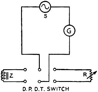
Fig. 1 - Schematic
S - Source of alternating current
G - Current-squared galvanometer
Z -Impedance being measured
R - Non-inductive variable resistor
The current-squared galvanometer is nothing more than a thermocouple type meter
which has a scale calibrated in 100 evenly spaced divisions of arbitrary value instead
of the usual logarithmic scale common to thermocouple type ammeters. The deflection
of the pointer is directly proportional to the square of the current and the scale
reading, therefore, is directly proportional to the power in the circuit. Standard
types of current-squared galvanometers require 115 to 125 ma. for full-scale deflection
and have a radio-frequency resistance of 4.5 ohms. The meter itself, therefore,
dissipates less than one-tenth watt at full-scale deflection. Because of its comparatively
small current capacity and low resistance, caution must be used in its handling.
This applies particularly to its use in making measurements of radio-frequency power,
especially in transmitters.
An instrument such as the Weston Model 425 or Jewell Pattern 67 thermo-galvanometer
is a most versatile aid in making measurements of alternating currents at practically
any frequency used for communication purposes.
A Neutralizing Indicator
As a device for use in neutralizing power-amplifier circuit, it is excelled only
by much more expensive and elaborate layouts. It is used in place of the usual flashlight
bulb and pick-up coils and in exactly the same way. A coil of one or two turns of
wire is connected to the terminals of the meter and placed in inductive relation
to the plate tank coil of the tube being neutralized. It is surprising how accurately
and quickly the minimum current adjustment can be found. One is sure that the set
is properly neutralized because there is the visual quantitative indication provided
by the meter scale as a basis for judgment. Again, the meter will cause less detuning
effect because it needs less current to operate it, the full-scale deflection requiring
only 125 ma. or less as compared to the usual 300 ma. necessary to light a flashlight
bulb to full brilliancy.
After all stages have been neutralized it is a simple matter to loosely couple
the meter to the output tank circuit and go over the transmitter tuning step by
step, tuning for maximum scale deflection of the meter always. The meter deflection
is very nearly proportional to the power output, because of the current-squared
feature, and the fixed resistance of the pick-up circuit. (P = I2R.)
One of these meters with its pick-up coil will take the place of several r.f.
ammeters in tank circuits, thus reducing the tank circuit resistance. It will also
be available for other uses, such as those mentioned below. By making inexpensive
fixed mountings - one beside each plate coil - the meter may be easily supported,
enabling one to be sure that any change in deflection is caused by a change in the
transmitter and not a change in position of the pick-up coil.
Other Audio- and Radio-Frequency Applications
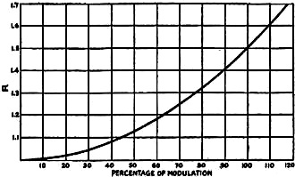
Fig. 2. - Graph of R vs. % Modulation
Other uses of the galvanometer are as a volume indicator; as a current indicator
in all a.c. measurements; as a resonance indicator in wavemeter circuits; and as
a means of measuring percentage of modulation.
A special transformer must be used with the meter if it is to be utilized as
a volume indicator in conjunction with audio-frequency amplifiers. This may be made
from an Amertran Type 854 50-henry choke, or any similar choke with enough room
in the core window to permit 80 turns of number 18 d.c.c. wire to be wound over
the coil. The large winding is then connected to the primary of the output transformer
of the amplifier and the meter is connected to the small 80-turn winding.
It will be noted that any transformer which has a secondary winding of the proper
impedance to match that of the meter (4.5 ohms) can be substituted for the one described
above, although it should have a high primary impedance in order to reduce the shunting
effect on the plate load impedance. The special transformer previously referred
to reduces the plate load impedance of the final stage of the amplifier by about
18.8%, which is certainly far from negligible. It would be better to connect a coupling
transformer of the proper ratio to the volume indicator, so that the tone quality
of the amplifier would remain unaltered. This, and the fact that at least one stage
of amplification is needed to operate it, are the only objectionable features of
the device.
There are numerous experiments and measurements found in the books listed by
the QST Book Department in which a galvanometer that will measure alternating current
of almost any frequency will prove valuable. The current-squared type is not too
large to be used in any of these experiments. Of course, a shunt may be used if
it proves to be too small.
A handy method of measuring impedance which is not found in many books uses some
sort of a.c. measuring instrument. The meter described is very good in this case.
To measure the impedance of a coil or condenser, or a combination of both, it is
only necessary to apply an alternating voltage of constant amplitude and frequency
to it and to measure the current flowing through it. A non-inductive variable resistor
is substituted for the impedance unit and adjusted until the same current flows.
The value of the resistance in ohms is the value of the impedance in ohms. The circuit
of the arrangement is that of Fig. 1.
Perhaps the original use to which the current-squared galvanometer was put was
that of resonance indicator in the absorption-type wavemeter . It is still used
on long-wave wavemeters; but the heterodyne frequency meter and the piezo-oscillator
have displaced such instruments in modern short-wave stations.
As a means of measuring the percentage of modulation, the galvanometer is by
far the most rapid instrument, although it is not accurate to a very high degree.
A full explanation of the method used in such measurements appeared in QST for May,
1930, on page 48. To make the employment of this method easier and faster, a curve
is given in Fig. 2 which was computed from the formula given in the article
referred to above. R is the same as the R in the article; the ratio of galvanometer
reading during modulation to that with no modulation.
* State University of Iowa, Iowa City, Iowa.
Posted May 6, 2022
(updated from original post on 8/24/2016)
|


