|
July 1953 QST
 Table of Contents Table of Contents
Wax nostalgic about and learn from the history of early electronics. See articles
from
QST, published December 1915 - present (visit ARRL
for info). All copyrights hereby acknowledged.
|
Neon bulbs used to show up in lots of commercial,
military, and consumer products, but have given way to LEDs because of efficiency
in cost, size, weight, and reliability. The 1950s-vintage radar I worked on in the
USAF used lots of them as indicators. Before the availability of Zener diodes, they
were used quite often as constant voltage references because of their characteristic
of maintaining a fairly steady voltage value over a wide range of currents. One
of the more useful tasks remaining for neon bulbs is for troubleshooting RF circuits
because of their ability to glow in the presence of a strong electromagnetic field
while only having physical contact with a single point in the circuit, or if the
field strength and frequency is accommodating, without any physical contact at all.
Some Ham radio operators still hang neon bulbs up on antenna masts where the feed
line interfaces to the antenna to use while adjusting impedance matching circuits
for maximum power transfer. Of course doing so generally requires the procedure
to be done at night, but that is usually not a hindrance to its usefulness.
Let's Use Neon Bulbs
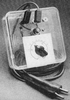
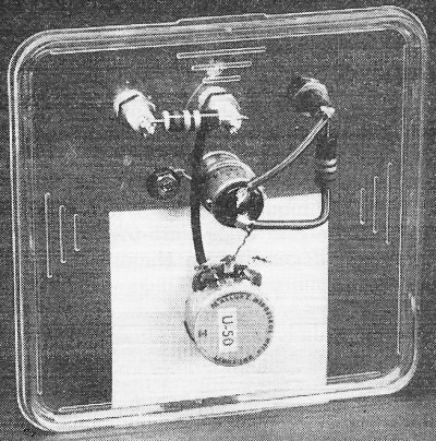
Top view of the neon bulb voltmeter. The calibrated dial was
mounted on a piece of cardboard and then mounted under the shaft nut of R2.
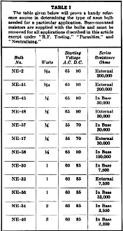
Table I
The table provides a handy reference source in determining the
type of neon bulb needed for a particular application. Base-mounted resistors arc
supplied with the bulbs and must be removed for all applications described in this
article except under "R.F. Testing," "Parasitics," and "Neutralizing."
Neon Bulbs in Applications as Indicators and Oscillators
By Lewis G. McCoy,* W1ICP
Many an experienced amateur has a soft spot in his heart for a simple little
device called a "neon bulb," and not without reason. This simplest of radio gadgets
is as useful as a third hand at a smorgasbord - W1ICP shows you why.
During a recent visit with a newly-licensed ham, we got to discussing his new
rig and some of the problems he was encountering while trying to get the "beast"
(as he put it!) working properly. The transmitter was a three-stage affair - oscillator,
buffer, and final amplifier - with about 100 watts input to the final. Considering
it was his first transmitter, he had done an excellent job of layout and wiring.
However, every time he turned the rig on, the final plate current would come up
to operating level and then drop back to zero, repeating this condition at about
two-second intervals. He had checked and double-checked his wiring but couldn't
find a thing wrong with the circuit, and was at a complete loss what to do next.
Having put all of his money into parts for the transmitter he hadn't been able to
afford a test meter of the volt-ohm-milliammeter variety. Our problem was then one
of finding out what was wrong with the rig with the materials he had available.
An inventory of his junk box turned up a small neon bulb and a couple of flashlight
bulbs. The neon bulb would serve for checking r.f. circuits while one of the flashlight
bulbs wired in series with a loop of wire could be used for checking resonance and
power in tunable circuits.1 His receiver was tuned to the oscillator
frequency and a good steady signal from the oscillator could be heard. It was immediately
apparent that the trouble in the transmitter was not coming from oscillator stage
difficulties.
The neon bulb was then held on the grid of the buffer and the bulb lit up, indicating
that r.f. was reaching the buffer. The neon bulb kept a steady glow as long as it
was held on the grid and there was none of the on-off characteristics that were
showing up in the output of the rig.
The buffer tank circuit was then tuned to resonance using the flashlight loop
for an indicator. A check with the neon bulb showed that all parts of the buffer
plate circuit seemed to be functioning properly. The neon bulb was then touched
to the grid of the final amplifier and it immediately indicated the "on-off" effect
that was taking place in the output. When the plate current would rise, the neon
bulb would light when the plate current dropped, the bulb would go out. It was fairly
obvious that the trouble was between the grid of the final and the plate of the
buffer. The trouble turned out to be the coupling condenser between the buffer plate
and the final grid. As soon as the condenser was replaced, the rig worked properly.
This was a case where a neon bulb proved to be a very efficient "gimmick" for trouble
shooting.
After this experience, the subject of various uses of neon bulbs was discussed
with other newcomers to the hobby. It was found that the majority of these amateurs,
and this included hams who have been licensed for a few years, had little or no
knowledge of the subject.
There is almost an infinite number of uses for neon bulbs and gaseous voltage
regulators in amateur radio, far too many, in fact, to try to list them all in one
article. However, some of the more popular uses are well worth bringing to the attention
of newcomers.
A neon bulb consists of two electrodes, or plates, separated by a small gap,
surrounded by neon gas, and enclosed in a glass envelope. When a voltage of enough
magnitude is applied to the electrodes, current will flow and the bulb will light
up with a reddish glow. The value of voltage necessary to cause the bulb to light
is called the starting voltage. One of the outstanding features of neon bulbs and
voltage regulator tubes is that the voltage drop across the tube will remain constant
over a moderately wide current range. In the case of voltage regulator tubes (VR
tubes) this current range is usually from about 5 to 40 ma. There are many applications
where a regulated low voltage is needed, and VR tubes are ideal in such cases. Complete
details on uses of VR tubes as voltage regulators are given in the voltage stabilization
section of The Radio Amateur's Handbook.
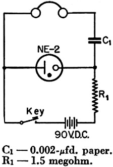
Fig. 1 - Circuit diagram for the code-practice oscillator.
However, our main interest in this article is not with neon bulbs used as voltage
regulators, but some hints and kinks for their uses in other applications.
Code-Practice Oscillator
Because a neon bulb will serve as an oscillator, a very simple code-practice
oscillator can be constructed using an NE-2 bulb. As can be seen from Fig. 1,
the code-practice oscillator consists of a neon bulb, condenser, resistor, 90-volt
d.c. power source, headphones and key. If batteries are used for a power source,
the smallest size batteries available will be sufficient for the purpose. The current
flow in the oscillator is less than 0.1 ma., so the batteries will last almost as
long as their normal shelf life.
If the audio note in the oscillator is not pleasing to your ear, it is possible
to increase the frequency of the note by changing C1 to 0.001 μfd.
or less. Increasing the value of C1 will lower the audio note.
If it is desired to use the oscillator as a keying monitor, the unit should be
connected to the key in such a manner so as not to affect the transmitter. This
can be accomplished by using a keying relay. It is worth mentioning in passing that
a good source for the NE-2 bulbs is discarded fluorescent light starters.
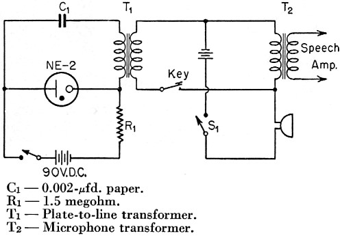
Tone Modulator
Another application for a neon bulb, particularly suited to the Novice interested
in 2-meter c.w. work, is a tone modulator. It should be explained, before going
further that, except for special purposes, tone modulation is only permitted on
11 meters, 6 meters and below. Fig. 2 shows the circuit diagram for this type
of modulator. T1 will be either a plate-to-single-grid or a plate-to-push-pull-grids
transformer, depending on the speech amplifier input. As with the code-practice
oscillator, the value of C1 can be changed to obtain a different tone.
By installing a switch, S1, between the key and the microphone input,
it is possible to switch the microphone out of the circuit.
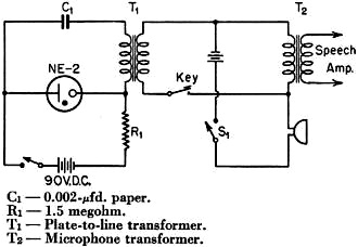
Fig. 2 - Circuit diagram for the tone modulator.
R. F. Testing
One of the most handy uses for neon bulbs is that of checking for the presence
of r.f. in a circuit. One of the characteristics of neon bulbs is that when they
are brought into close proximity with an r.f. field, they will glow. It isn't necessary
for the bulb to be connected directly to the circuit for this phenomenon to take
place. If the field is strong enough, the neon bulb will light without direct connections.
For example, it is possible to hold a small neon tube such as an NE-2 or NE-45 by
the glass bulb, with the base touching "hot" portions of an oscillator plate circuit
and, if there is r.f. present, the bulb will glow. It is even possible in some cases
to have one of the small bulbs glow when touched to the crystal contacts in a crystal
oscillator. It is obvious how useful such an indicator would be for checking to
see if various circuits in a transmitter are working. By starting at the oscillator
and working through the transmitter right up to the output, it can be quickly determined
if there is r.f. present at the input and output of each stage.

Bottom view of the voltmeter showing the place-ment of parts.
No socket was used for the neon bulb. A stiff loop of wire is soldered to the side
of the bulb shank and the end of the loop is mounted under a uut and bolt in order
to hold the bulb solid. The leads to the base contacts of the neon bulb are soldered
directly to the base contacts. Caution should be observed in soldering so that the
contacts are not shorted to the bulb shank.
Testing for Parasitics
Another useful characteristic of neon bulbs when checking r.f. is the color of
the neon gas when it glows. At low frequencies, the color is in the red spectrum.
At very high frequencies, from approximately 50 Mc. and up, the color becomes violet
or purple. This is useful in determining the frequency of a parasitic. There are
two common types of parasitics that plague hams, low-frequency parasitics, usually
between 30 to 1200 kc., and very high-frequency parasitics which are usually between
100 to 200 Mc. The method for this type of testing is simple. When an amplifier
is "taking off," or to be more explicit, when there is r.f. output with no excitation
from a previous stage, it is quite possible that the cause is due to parasitic oscillation.
A neon bulb touched to the output of such a stage will show either a reddish or
purplish glow. If it shows red, then one should look for a low-frequency parasitic,
while if it shows purple, look for a v.h.f. parasitic. Incidentally, 807 r.f. amplifiers
are particularly subject to v.h.f. parasitics. However, a word of caution - be sure
that you are using a neon bulb for such a check; there are bulbs available that
are filled with argon gas and they will glow blue or purple at low frequencies.
The designations on argon bulbs are AR, while for neon it is NE. The cause and cure
of parasitics is described in detail in The Radio Amateur's Handbook.
Neutralizing Indicator
Another handy use for a neon bulb is indicating the need for neutralization of
the tank circuit of an amplifier. With the plate and screen voltages disconnected,
but with the preceding stages running, touch the base of a neon bulb to the plate
tank coil and tune the tank condenser through resonance. If the neon bulb lights,
it usually means the amplifier needs to be neutralized. With the neon bulb lit,
adjust the neutralizing condenser until the bulb goes out. Tune the plate tank condenser
through resonance again to make sure the bulb stays out. This is a useful test,
but it is not the most sensitive-neutralizing test there is, particularly for a
low-powered transmitter.
Neon bulbs can also be used as indicators for showing r.f. voltage in antenna
feeders. When coupled close to antenna feeders, the neon bulb will glow. Maximum
brilliance in the neon bulb indicates maximum voltage at the feeders. Keeping an
eye on the neon bulb, it becomes a simple matter to tune the transmitter and antenna
coupler for maximum output.
Fixed Bias Source
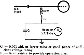
Fig. 3 - Circuit diagram for bias supply.
A system for obtaining fixed bias that is used by many hams is shown in Fig. 3.
This system eliminates the need for a fixed bias power supply but still provides
fixed bias! The neon bulb or VR tube used in the circuit will depend on the grid
voltage and current needed to excite the stage being biased. When the grid driving
voltage is applied to the stage, the neon bulb is lighted, and a charge is put on
the condenser, C1. 'When the excitation voltage is removed, or the key
is opened, the neon bulb goes out and the voltage charge that remains in the condenser
acts to keep the amplifier tube biased. The charge on the condenser has been known
to hold protective bias for as long as 8 hours. Whenever the transmitter is turned
on, excitation voltage should be applied to the grid to charge the condenser before
turning on the amplifier plate voltage. This is an inexpensive method for obtaining
fixed bias and is easy to install.
Receiver Protection
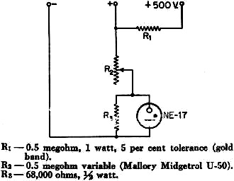
Fig. 4 - Circuit diagram for the neon bulb voltmeter.
Probably one of the most common uses of neon bulbs is that of protecting receiver
inputs from damage by surges of r.f. voltage. With receivers using a two-wire input
at the receiver terminals, the best protection is obtained by installing two 1/4
-watt neon bulbs. One neon bulb is connected with one of its leads to the antenna
terminal and the other lead to the chassis and the other bulb is connected in the
same manner to the other antenna terminal. In the case of a single-wire antenna
lead, one neon bulb is connected with one lead to the antenna terminal and the other
lead to the chassis. When an r.f. voltage exceeding the starting point of the neon
bulb is developed across the antenna terminals, the bulb will ignite. This affords
a measure of protection for the receiver input because the r.f. voltage is usually
reduced to a point where the receiver can handle it.
An A.C.-D.C. Neon Voltmeter
This last gadget using a neon bulb could truthfully be called the "piece de resistance"
because of its usefulness and low cost. Most newcomers to amateur radio put all
their money into their transmitters and receivers and have little of the green stuff
left for purchasing test equipment. One of the most important test instruments around
the shack is a device called a voltmeter, for measuring a.c. and d.c. voltages.
Fig. 4 shows the circuit diagram for a very simple low-cost neon indicator
that will measure any a.c. voltage between 100 and 900 volts, and any d.c. voltage
between 100 and 1000 volts.
The voltmeter uses an NE-17 neon bulb for an indicator as this particular type
has a lower starting voltage than most other types. The lid of a plastic sandwich
box was used as a chassis for the voltmeter described here. This makes an inexpensive
mounting and affords excellent insulation. Whatever type of chassis is used in constructing
the voltmeter, be sure to allow a 2 1/2-inch square space around the shaft of R2.
This will allow enough space to accommodate the drawing of the calibrated voltmeter
dial that is included in this article. The drawing can be traced or cut out and
then mounted on a piece of stiff cardboard. Several different NE-17 bulbs were tried
in the unit described here and all showed the same starting voltage, so the dial
calibrations should hold true for any units that are constructed according to Fig. 4.
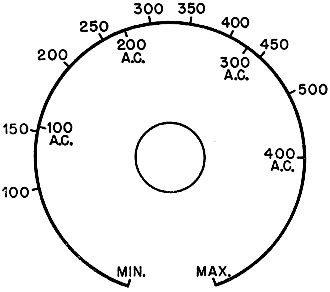
Fig. 5 - Drawing of a dial scale for the neon bulb voltmeter.
This scale can be traced on another piece of paper or cut out and mounted on a piece
of cardboard and used in the voltmeter construction.
The base contact of the NE-17 should be wired so glow appears around the outer
electrode when a positive voltage is applied to the positive terminal of the voltmeter.
If the inner plate glows first when correct polarity is applied to the positive
and negative terminals, the calibrated dial will read higher on all voltages checked.
It should also be pointed out that if a different potentiometer than the Mallory
U-50 is used for R2, an entirely different calibration might be necessary.
In such a case, it would be necessary to calibrate a dial using known voltages for
check points.
The operation of the neon voltmeter is simple. When an unknown voltage is to
be checked, R2 should be first set at maximum. Insulated leads are then
connected to the positive and negative sides of the unknown voltage. The knob on
R2 is then very slowly turned toward minimum until the neon bulb lights.
At the exact point the bulb glows, the value of the unknown voltage can be observed.
Do not turn the knob any farther than is necessary to cause the bulb to glow because
if excessive current is allowed to flow through the bulb, there is danger the neon
bulb will arc and burn out. Always start your check with the knob on R2
turned to maximum voltage or above the voltage you intend to check. In other words,
the same precautions should be observed with this type voltmeter as with any other
kind - always use the highest voltage-ranges and check down to an unknown voltage
in order to protect the testing device. The "over 500 volts" terminal marked +500
v. in Fig. 4 should be used for checking any potentials above 500 volts. When
using this terminal, add 500 volts to whatever reading appears on the dial. If the
reading is 150 volts when the 500-volt tap is being used, the voltage being checked
would be 650 volts. And remember, in testing voltages, treat all voltages with the
utmost respect. They can be deadlier than an irritated rattlesnake when you become
careless.
In conclusion, many additional applications for neon bulbs will become apparent
after you use them for a while. If you come across ideas you think the rest of the
gang would be interested in, send them along to Hints and Kinks.
* Technical Assistant, QST.
1 McCoy, "The Tune-Up Loop," QST, Dec., 1952, p. 37.
Posted April 21, 2022
(updated from original post on 6/9/2016)
|