April 1945 QST
 Table
of Contents Table
of Contents
Wax nostalgic about and learn from the history of early electronics. See articles
from
QST, published December 1915 - present (visit ARRL
for info). All copyrights hereby acknowledged.
|
The first recorded successful
parachute jump was made from a hot air balloon in 1797 by Frenchman
André-Jacques
Garnerin. His performance elicited "a scream of terror" from the crowd below
and even caused women to faint at the sight of his basket swinging wildly beneath
the canopy. Many brave souls met with less success before and after that jump. By
World War II the state of the art for parachutes had managed to cure the wild
swing problem, but reliability still left a lot to be desired, especially when the
'chutes were packed by paratroopers with only a few weeks of experience. Control
during the descent was rather limited due to the original round configuration with
directional commands effected by pulling on the shroud lines on one side or the
other. Getting to the ground safely with a field pack and a rifle strapped to you
involved a lot of luck. It required even more luck to land with tube-powered radio
gear of any sort. Bulky and heavy was the norm, particularly if any amount of battle
ruggedness was built in. Massive high voltage transformers and lead-acid batteries
pushed the limit of the definition of 'portable.' The 'Para-Talkie' was designed
to address those problems. Three vacuum tubes, a single transformer, and associated
circuitry fit in a 3x4x5-inch metal case that looked like a Bud project box, with
an A-size battery cell and a couple B-size cells strapped to the bottom. A 1/4-wave
braided wire antenna ran down to the soldier's boot allowing him to communicate
during the descent and while on the move on the ground. It was quite an accomplishment
for the time.
The "Para-Talkie"
A Parachutist's Transceiver
By L.T. Arthur H. Copland, CAP
Communications Officer. Parachute Group 639, 18419 Santa Rosa Dr., Detroit, 21,
Mich.
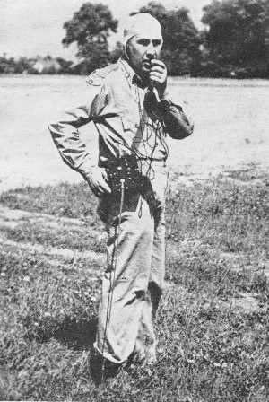
The para-talkie is given a test in the field by Lt. Ralph Berkhausen, CAP, using
the special parachutist's antenna attached to his leg. (for some reason this guy
reminds me of Nicholas Cage)
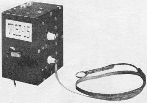
The" para-talkie" with flexible braid antenna attached. The change-over switch
is in front, the power switch on the bottom, and the headphone and mike connectors
on top, The extra stand-off insulator is provided for supporting a whip-type antenna
for ground use.
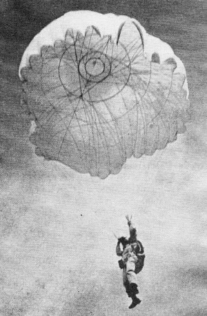
A 'chutist is aided in his descent by instructions received via the para-talkie,
which he carries strapped to his body.
When parachute instructors of a Michigan CAP wing wanted some means of communicating
with student jumpers in the air, the radio crew set out to solve the problem. The
result was the development of the tiny transceiver unit described in this article.
The acorn-type detector-oscillator tube and the two miniature audio tubes operate
from a pair of midget-sized 33-volt "B" batteries and a single flashlight cell.
A rig of this type also will find many applications in WERS and ham work on terra
firma.
Communications problems in the v.h.f. band shared by CAP and WERS seem, for the
most part, to parallel those experienced in OCD-WERS operation. One CAP Group -
Parachute Group 9 of Michigan Wing - by virtue of the unique nature of its curriculum,
however, confronted its communications personnel with an unusual problem to solve.
Parachute instructors clamored for some means of communicating with student jumpers
to provide a greater measure of safety and, at the same time, to give the student
the advantage of receiving direct instructions in manipulating his chute to control
his descent. Limited success along these lines was effected by the use of directional
loudspeakers, but the disadvantages were many. Two-way radiotelephone contact seemed
to be the only answer to the need, but to our knowledge this had never been successfully
accomplished between 'chutist and ground. No enlightening technical information
on v.h.f. equipment for parachute being found in the books, the group communications
staff set out to do a little pioneering.
Existing units of the walkie-talkie type would not serve for obvious reasons.
Any set carried by a parachute jumper must be small and light, and yet it must be
rugged enough to withstand the shocks of landing. A whip antenna could not be used
because it would be a hazard; therefore the antenna would have to be of flexible
material and radiate efficiently while being carried close to the body. Power and
transceiver controls would have to be placed so that they could not be shifted accidentally.
Experimental Tests
With the above problems in mind, a basic experimental circuit was set down on
paper and technicians of our squadron communications sections were directed to work
out their own concepts of the ideal parachutist's transceiver. That's when the fun
began! Dreams like this, we found, were not easy to make come true. Many of the
boys were doomed to disappointment when their pet creations either were rejected
by the parachute instructors as a hazard to the jumper or could not be persuaded
to develop any acceptable degree of signal strength. Eddie Pietrasik, deputy communications
officer of Hamtramck Squadron 639-3, was the ingenious lad who developed the neat,
sturdy transceiver which is the subject of this article.
After exacting ground tests, an aerial test was made during a routine CAP maneuver.
Equipped with the new transceiver, Lt. Ralph Berkhausen bailed out at 3500 feet
and established continuous two-way contact with Lt. James Allen on the ground from
the instant his 'chute filled until he hit the field. Lt. Allen, the group's master
parachute instructor, who was using an Abbot DK-2, was exultant. Communication had
been perfect. Here at last was the perfect instruction medium which he and his staff
had so long hoped for. To his knowledge, and to ours, this was the first time two-way
radiotelephone had been used successfully by parachutists. It was he who christened
the unit the "para-talkie."
The para-talkie is fastened under the jumper's right arm, near the belt, by means
of webb straps threaded through slots in the rear plate of the case. The straps
buckle over the left shoulder and under the right groin. Microphone and headphone
cords are attached at the rear top of the case. They run under the 'chute harness
to the jumper's coverall opening, then inside the coveralls to emerge from the collar
near the 'chutists ear. A tiny lapel crystal mike, clamped on the inside of the
helmet chin strap, is used as a throat mike. Lightweight headphones with headband
removed are attached inside the helmet.
The antenna is a piece of flat metal shield braid, approximately a quarter-wavelength
long. A lug is securely soldered at one end and this is attached to the lead-in
near the bottom front of the case, the braid running down to the toe of the 'chutist's
right boot. At the boot there is a special harness and an adjustable expansion spring
which keeps the braid taut and also compensates for long or short legs. This is
insulated from the braid by a short polystyrene bar.
The set is pre-tuned to 115.75 Mc. Before the jumper leaves the airplane he turns
on the set by snapping a toggle switch on the bottom of the case. The controls normally
are in the" receive" position. He can then hear transmissions from the ground transmitter.
To talk to his instructor he presses the "push-to-talk" lever at the right side
of the case. The "receive" position is automatically returned when he releases the
lever.
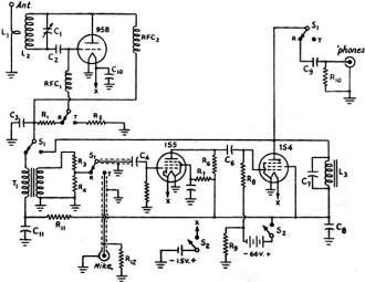
Fig. 1 - Circuit diagram of the para-talkie.
C1 - Isolantite-insulated midget tuning condenser, 3 plates, with
slotted shaft. C2 - 50-μμfd. mica. C3, C4
- 0.005-μfd. mica. C5, C10, C11 - 0.1μfd. paper. C6
- 500-μμfd. paper. C7 - 0.002.μfd. paper. C8 -10-μfd.
75-volt electrolytic. C9 - 0.1-μfd. paper. R1, R12
- 5 megohms, 1/2 watt. R2, R4 - 25,000 ohms, 1/2 watt.
R3 - 0.5 megohm, 1/2 watt. R5 - 10 megohms, 1/2 watt.
R6 - 1 megohm, 1/2 watt. R7 - 3 megohms, 1/2 watt.
R8 - 2 megohms, 1/2 watt. R9 - 450 ohms, 1/2 watt. R10
- 1,000 ohms, 1/2 watt, R11 - 25,000 ohms, 1 watt.
L 1 - 1 turn No. 14 bare copper wire, 1/2-inch inside diameter. L2
- 4 turns No. 14 bare copper wire, 1/2-inch inside diameter, spaced to fill 1/2-inch
winding length. L3 - Modulation choke, 30 henrys, 5 ma. (Thordarson
74C30 can be used if space is available.)
RFC1, RFC2- V.h.f. choke, 55 turns No. 30 d.s.c., wound on
3/16-inch polystyrene rod (or Ohmite Z-1). S1 - Pole of 4-pole, double-throw
rotary wafer switch with spring return and lever. S2 - Pole of d.p.s.t,
toggle switch.
Headphones used are Brush Type BJ. Any good quality light weight type may be
substituted. The microphone is an Astatic L-I. The "B" batteries are Burgess XX22E
and the "A" battery a No. 2 flashlight cell.
Circuit Details
The circuit diagram of the transceiver is shown in Fig. 1. The oscillator-detector
circuit is built around a 958 acorn tube which operates as an ultraudion when transmitting.
Resistor R2 develops bias voltage for the grid. Condenser C10,
connected across the filament terminals of the 958, was necessary to eliminate a
tendency toward spurious audio-frequency oscillation.
The receiving circuit is the usual self-quenched superregenerative-detector type,
with a positive exciting voltage applied to the grid of the 958 through the resistor
R1. C3 is in the quench frequency-determining circuit and
the capacity necessary, dependent to some degree upon inductance of the primary
of T1, might vary from the value indicated with a different transformer.
Two stages of audio are used, with transformer coupling between the detector and
the first stage and resistance coupling between the first and second stages. Full
gain is not required for receiving. The grid of the first audio amplifier is fed
from a voltage divider across the secondary of T1, tapped down as indicated,
so that the voltage amplification realized from the 1S5 does not over-drive the
grid of the IS4. This arrangement also helps to guard against r.f. on the grid of
the 1S5. The 1000-ohm resistor, R10, shunting the 'phones is another
attenuating device to hold the volume down to a level where the headset can be worn
with comfort. In early stages of the development of this rig, a switching arrangement
was used which cut out the 1S5 and coupled T1 directly to the grid of
the 1S4 through C6. The revised circuit arrangement, although employing
considerable attenuation, is much more satisfactory.
Modulation is accomplished by employing a choke in the common high-voltage line
to the modulator tube and the 958 plate. This choke has a d.c. resistance of 1000
ohms and is by-passed by C7 to avoid oscillation in the 1S4. Grid bias
for the 1S4 and 1S5 is obtained by the voltage drop across R9 between
negative "B" and "ground." The antenna-coupling turn is placed at the grid end of
the tank and coupling is adjusted for the maximum antenna loading which will allow
the tube to maintain stable superregeneration when the switch is in the "receive"
position.
Construction
The unit is contained in a standard 4 X 5 X 6- inch steel box with removable
sides. Most of the components are mounted directly on one of these removable sides,
to make the job of assembling and wiring easier.
To permit the shortest leads possible, the acorn detector-oscillator tube and
the tuned-circuit components are grouped close to the change-over switch mounted
on one of the fixed sides of the box. C1 is mounted on spacers, with
its shaft opposite a quarter-inch hole through which it is adjusted by a screwdriver.
L2 is self-supporting, its ends being soldered directly to the terminals
of C11 with the grid side going to the rotor terminal. L1
also is self-supporting, being mounted at the grid end of L2. An extension
lead at one end goes directly to the small feed-through insulator which serves as
the antenna terminal, while the other end is soldered to a lug fastened to the case.
RFC2 is supported by the heavy leads with which it is fitted, one being
soldered to the plate terminal of the 958 socket while the other goes to the switch
terminal RFC1 is mounted similarly underneath the change-over switch.
The audio transformer, T1, is in one corner next to the change-over
switch. The two audio tubes are placed opposite S1, leaving sufficient
space behind them for the two 33-volt "B" batteries which are held in place with
metal straps. Space for the miniature modulation choke, L3, is found
next to the 1S4 output tube. The single-cell "A" battery is clamped against the
bottom end of the case with a U-shaped metal strap.
Two cable connectors are set in the top of the case. One is for the headphone
connection and the other for the microphone cord. It is important that a shielded
'phone cord be used. The power toggle switch, S2, is mounted on the bottom
end. The side of the case which was removed for the photographs is slotted for the
web straps by which the unit is fastened to the operator.
The para-talkie has held up well under repeated tests, our only casualty being
one cracked lead-in insulator. Careful selection of parts and a painstaking wiring
job probably are responsible for its stable operation, the frequency shift from
"receive" to "transmit" being negligible. Its general performance as a portable
rig on the ground, using a whip antenna, is superior to commercial transceivers
with considerably greater power input.
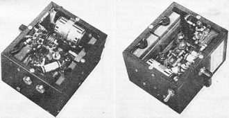
These views of the "para-talkie" show the arrangement of components
inside the 4 x 5 x 6-inch steel box.
Posted January 8, 2021
|