|
February 1953 QST
 Table
of Contents Table
of Contents
Wax nostalgic about and learn from the history of early electronics. See articles
from
QST, published December 1915 - present (visit ARRL
for info). All copyrights hereby acknowledged.
|
This is one of the earliest examples
I have seen (and I've seen many) of an electronics article that was written in a
conversational tone rather than in the typical stoic, all-business, just-the-facts
type prose. In fact, you would be hard pressed to discern it from a contemporary
article in QST magazine. Author Davis describes his process of interfacing
52 Ω coaxial cable to a multi-element beam antenna. The gamma match has
the advantage in such an application of being usable when the center of a driven
element is directly grounded to the antenna boom. Most other types of feed systems
require that the driven element be isolated from the boom. BTW, SWR ratios are written
here with slashes as the ratio component separator rather than a colon; that is
2:1 is written as 2/1.
Practical Adjustment of the Gamma Match
Feeding the "Plumber's Delight" with Coax
By Warren H. Davis, W6IBD

A plastic fruit-juice container makes a good weather protector
for the variable condenser.
Although many articles have been written on the subject of parasitic-beam adjustment,
there are still many who are puzzled as to the relative importance of the various
factors involved in attaining optimum performance. But no matter how much you have
studied the subject, we believe that you will find the experiences of W6IBD, in
feeding the plumber's-delight type 3-element beam with coax cable, most interesting.
Articles on antennas are as old as ham radio itself. Therefore, it is not my
intention to present anything sensational for the beam I am about to describe, but
I would like to state that it works as well as any beam it has ever competed against.
I use the word "competed" because there is no other way really to check an antenna
if you are a DX man.
The competition in this case was supplied by some of our better known local stations,
namely: W6FSJ, 3 elements, 50 feet high; W6ENV; 3 elements, 65 feet high; W6SN,
3 elements, 65 feet high; and W6CYI, 3 elements, 60 feet high. Of these four stations
mentioned, two are very active in DX contests and three of them have worked more
than 240 countries. They are all very rough in any dogfight.
In the recent DX contest, most of these gentlemen waited for me to finish, then
they took their respective turns. Upon occasion I, too, would wait for them, but
not too often. Now, considering that we all run about the same power, all live within
a fifteen-mile radius, and all think we are the world's best DX operators, the obvious
conclusion is that our beams, for all practical purposes, work equally well. Therefore,
the only claim that I can make for my beam is that it is the easiest to build, which
I consider a prime factor to be considered by any ham.
Feed System
The part of the beam that usually is the worst to build and to make work is the
feed system and the matching device or driven element. Two of the above-mentioned
rascals use one method of feed system and matching, and the other two use another.
W6FSJ and W6CYI use folded dipoles and two pieces of RG-8/U to feed them. W6ENV
and W6SN both use split driven elements. W6ENV uses a single piece of RG-8/U to
feed his, and W6SN uses a quarter-wave matching section, then 600-ohm line.
Well, I ask you, which is the easiest type of line to feed into the modern well-shielded
TVI-free final amplifier? Naturally, anyone in his right mind would choose a single
piece of coax. W6ENV, Andy Eisner, took the honors here - that is what he uses.
Several months ago when I decided to build this beam, that was what I decided
to use. Andy assured me that he had never experienced any trouble with unbalance,
and he thought it was great. However, I did not like to think of the reasonably
difficult problems of attaching a split driven element to the 2 1/2-inch square
aluminum boom that I proudly possessed. Moreover, I did not wish to detune the parasitic
elements of my beam to raise the center impedance to meet that of 52-ohm coax, although
this in itself will not hurt the operation of a beam if the correct spacing is used.
By the way, I am glad I added that last statement; it should get me off the hook
for implying that Andy's beam is a mess.
The next step was to decide what type of match could be used to feed a piece
of 52-ohm coax into a plumber's-delight type of beam. A plumber's-delight was decided
upon because there was no question in my mind that this was the easiest to build.
However, feeding a beam of this type with coax line presents a few problems, such
as balanced feed, obtaining a low standing-wave ratio, and the actual mechanics
of obtaining these desirable features. There was one other feature that I desired
in this beam. It was that the beam must be resonant in the 14-Mc. band. This is
not a prime factor for good operation of the beam itself, although it should be
reasonably close to resonance. But it is necessary for a low standing-wave ratio
and good coax efficiency.
The obvious choice for my beam was a gamma match. This, with a few refinements,
is what I have used. A few articles have appeared on this type of match but they
seem to present no details of how they should be tuned, nor do they tell the performance
data on a beam using this match, such as what is the bandwidth of the usable standing-wave
ratio. When running high power into RG-8/U that has a low-pass filter in it, the
s.w.r. should not be over certain limits. Therefore, I decided to run some experiments
with a gamma match and see just how good it really was.
Element Spacing
Some months before all of this brain work started, my child bride and myself
had rented a house only 300 yards from W6SN. This, in itself, was a mistake, but
it was the only habitation available at the time. The house did not come equipped
with poles for antennas, but it was owned by a lady who said that I could put up
one small pole for my wireless if I would promise to remove it when leaving. This
promise was very glibly given and in we moved.
Immediately after this event, my beam was attached to a piece of pipe, and placed
in a vent pipe on top of the house where it was approximately 25 feet above the
ground, but could still be reached when standing on the roof of the second story.
This was, of course, an ideal place to tinker with the beam and its matching device.
If you will refer to the diagram of Fig. 1, you. will see that the beam
has a 22-foot boom and that the reflector is spaced closer than the director. I
do not believe that this is any better than when the reverse is true, as in most
beams, but the center impedance of a beam is slightly higher when the director is
spaced farther than the reflector. The spacing of this beam is approximately R-0.15
and D-0.2.
In spite of the volumes written on beam spacings, if a beam is resonant in the
band where you wish it to work, the director is tuned to a frequency higher than
that of the driven element, the reflector is tuned to a lower frequency, and the
beam is fed properly, it will in all probability get out as well as any other beam
with the same number of elements at the same height, regardless of spacing. However,
beams with wider spacing do have a higher impedance and slightly better bandwidth,
so I tried to go down the middle of the road so far as boom length goes.
Adjustment of Gamma Match
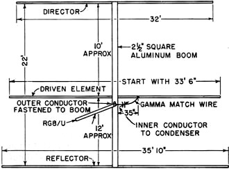
Fig. 1 - Sketch of W6IBD's "plumber's-delight" beam antenna
with dimensions for the 14-Mc. band. The use of the variable condenser is discussed
in the text.
After erecting the beam on its pipe in the roof, I grounded the braid of the
coax to the boom, directly under the center of the driven element and connected
the center wire to a piece of aluminum tubing that ran out under the driven element
about four feet. The end of this small piece of tubing was then connected to the
upper tubing by a brass clamp that could slide back and forth to vary the point
of attachment for the gamma match. The driven element at this point was 2 1/2 inches
in diameter and the gamma match was 1 inch in diameter, and spaced approximately
5 inches from the element.
After considerable checking with my trusty coax-line standing-wave indicator
in the line, at long last I discovered what others before me had learned - it won't
work; that is, the standing-wave ratio cannot be made low enough at the resonant
point of the beam. This is probably true because it is very difficult to get the
correct ratio of tubing size to spacing between the matching system and the driven
element, plus the fact that the point at which the gamma match is attached to the
element is critical if there is reactance. And, believe me, there is.
Therefore, the next step was to put a variable capacitor in series with the center
wire of the coax and the gamma match. This was better, but not quite as good as
I had expected. I could get the standing-wave ratio down quite low, but the beam
was resonant outside of the band; and when I changed the length of the driven element
of the gamma match to pull the resonant point back into the band, the standing-wave
ratio was again kaput. This got to be very tiring, so I tore off the tubing that
made up the gamma match and replaced it with a piece of No. 10 wire. This piece
of wire merely looped from the capacitor up to the driven element and was attached
to a point approximately 35 inches from the center of same. Immediately things began
to get better. The s.w.r. was now 2/1 at 13.5 Mc. and dropped as I approached the
center of the band, rising again to about 3/1 at 14.3 Mc. The piece of wire I used
between the condenser and gamma tap was about 33 inches long. The length of this
wire has an influence on the tapping point, so if the length is changed, a different
tapping point must be used.
By the way, the condenser being used was a 120-μμ'fd. variable with 1/8-inch
spacing. This was considered adequate to tune out the reactance of the gamma match
and, since it was located at a low-voltage point, the spacing should be enough.
We found we were correct on both accounts.
Once the wire was installed and the s.w.r. found to be as stated above, I decided
to make the beam resonant in the middle of the band and to make the s.w.r. as low
as possible. Actually, all that I did was to shorten the driven element a bit on
each side, then, keeping my eye on the s.w.r. meter, I tuned the capacitor and the
needle dropped almost to zero. This was the equivalent of about 1.4/1 s.w.r. A series
of measurements was then taken from about 13.5 Mc. to 14.4 Mc. The point of lowest
s.w.r. was found to be at 14.150 Mc., and the s.w.r. at this point was as near to
1/1 as anyone could ever hope to get a beam. This is also the resonant point of
the beam, and this resonant point is always found at the point of lowest s.w.r.,
regardless of what the s.w.r. may be.
When checking the bandwidth of the beam, it was learned that it was 2/1 at 13.990
Mc. moving downward to its low point at 14.150 Mc. and then moving upward to 2/1
at 14.450. Mc. The low point, as stated before, was about 1.1 to 1. There is no
question that a folded dipole would be better, but think of the extra work involved
in construction, to say nothing of the fact that two wires are necessary to feed
it.
What about the losses at 2/1 s.w.r.? Well, at 14 Mc., which is where s.w.r. is
almost, but not quite, that amount, the loss in the line using 100 feet of RG-8/U
is 0.75 db. This I refuse to worry about.
Element Length
The next month was spent in changing the lengths of the various elements to see
if I could raise the gain, or perhaps improve the front-to-back ratio. This latter
could be done, but the forward gain always remained about the same, so long as the
reflector and the director were not detuned too far from the frequency of the driven
element. Incidentally, after each adjustment of the elements, it was only necessary
to change the length of the driven element slightly one way or the other and to
touch up the condenser on the beam, and the antenna would be back in the band with
the s.w.r. back to normal.
I also tried moving the point of attachment of the gamma match to the beam back
and forth. This would make a difference in the s.w.r. and the resonant point of
the beam, but not as much as I had expected. I finally left it at 35 inches.
By this time I was sick and tired of spending half of my waking hours on the
roof, so the director was set at 14.3 Mc. and the reflector at 14 Mc. The s.w.r.
indicator was inserted in the line about 15 feet from the beam. After checking the
s.w.r., the beam. was found to be resonant at about 14.3 Mc. I merely lengthened
the driven element an inch or so on each side, trimmed up the condenser while watching
the meter, and -presto! - we were back in the middle of the band with the previously-mentioned
excellent s.w.r.
Feeling that it was necessary to keep our gentle Los Angeles rains off my precious
condenser, I mounted it upside down in a plastic fruit-juice container that was
mounted on the side of the boom just under the driven element. This did the trick;
the job was done. The sad part of this entire affair was that after weeks of fooling
around with this beam, my final results were the same as the ones I had in the beginning.
Summary
In conclusion, let me say that this match can be attached to any beam that has
an unbroken driven element. The director and the reflector should be set by the
charts in the ARRL Handbook. They may be tuned, if you wish, but it is your time
that is being wasted, not mine. The driven element should be set initially for the
center of the band by the chart in the Handbook and the gamma match, consisting
of a condenser and a piece of No. 10 wire, attached to the driven element. This
point of attachment is about 35 inches from the center of same. A section of 52-ohm
coax, with the s.w.r. indicator inserted in it, should be attached to the beam;
the braid is grounded to the center of the boom directly under the center of the
driven element, and the center wire of the coax is attached to one side of the capacitor.
A VFO should be fed into the coax. Set the frequency in the middle of the band and
adjust the capacitor to give the lowest s.w.r. Then, run a series of checks across
the band to find the resonant point of the beam. If that point is not where you
want it, either lengthen or shorten the driven element. Leave the parasitic elements
as they are. If a complete null cannot be obtained, it may be necessary to change
the point of attachment on the driven element slightly. This should do it; you are
now in business.
The photograph shows how the match and its plastic container looks on my beam.
This particular set-up will take a kw. of 'phone and several on c.w.
By the way, in spite of the fact that I had the highest score on 14 Mc. in the
Southern California area, I was severely thrashed by W6BAX in Northern California
during the last DX contest. Believe me, if Opie would only move south to this land
of half-hour European openings I would fix his wagon.
Oh yes, my beam is now on a small pole 57 feet high, and my landlady is really
flabbergasted!
Posted June 14, 2021
(updated from original post on 6/23/2015)
|


