Practical Consideration and Application in a Multielement Quad |
|
Multielement quad antennas are as popular today as they were in 1967 when this article appeared in the ARRL's QST magazine. That is not to say they are common. This particular design is for the 10-, 15-, and 20-meters bands, all three of which are still in use today. If you build a multielement quad as shown here, you might want to find a substitute for the bamboo frame members; aluminum tubing is pretty cheap, but if you use metal, you'll need to use insulators at the connection points. Formulas are provided for determining element lengths and director and reflector spacings if you want to design to an alternate specific frequency or band. Practical Consideration and Application in a Multielement Quad By Roderick M. Fitz-Randolph, W5HVV/7
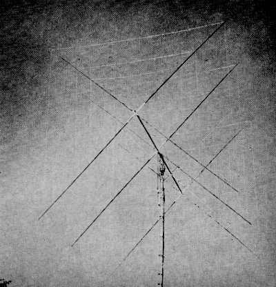
The three-band quad shown in its completed form, installed and ready to use.
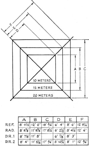
Fig. 1 - Element dimensions in feet and inches for the three-band quad.
Fig. 2 - Element layout and spacing in terms of feet and inches, and in wavelength. The plastic boxes that contain the gamma-match capacitors are shown adjacent to the tower.
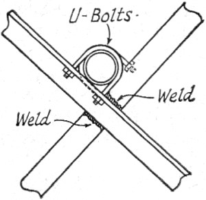
Fig. 3 - Sketch of the spider and boom assembly technique. The spiders are made from sections of angle iron and are welded together as shown.
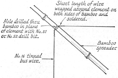
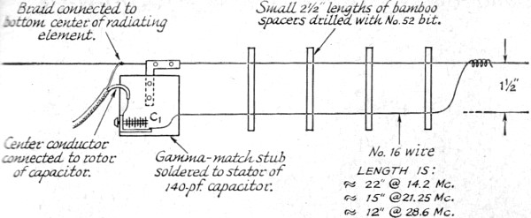
Fig. 5 - Method by which the quad wire elements are attached to the bamboo spreaders. Building a three-band cubical quad antenna is not the easiest task in the world. This article describes such an antenna which is the by-product of many hours of hard work and testing. W5HVV shows how to build the antenna, how to tune it up, and what kind of results to expect when it is put to use on 20, 15, and 10 meters. It has been the author's experience that the 3-db. gain increase for twice the number of parasitic elements applies to the quad as well as to the Yagi beams. When a director of the proper dimension is added to the normal radiator-and-reflector quad configuration, one may expect an approximate 3-db. increase in gain. By adding a second director, an increase on the order of 1.75 db. may be expected. More directors net a corresponding decrease in additional gain for each director added. For example, the theoretical increase in gain by adding a third director is 1.25 db. To achieve a 3-db. gain over a four-element quad, a seven-element quad would have to be constructed. The boom length required for such an antenna all but makes it impossible to construct. It is quite impractical for the amateur to seriously consider. The quad constructed by the author and herein described has four elements on 10 meters, four elements on 15 meters, and three elements on 20 meters. An additional element on 20 meters with the same boom length would have worked to disadvantage, because the directors would have been too closely spaced to operate properly and efficiently. Spacing Element spacing, in terms of wavelength, is perhaps not quite such a controversial subject. Most will agree that the wider the spacing, up to approximately one-quarter wavelength, the greater the gain and the higher will be the impedance at the feed point of the antenna. In the author's opinion, an optimum boom length for a tri-band quad would be about 24 feet. This would allow for a spacing of 0.2, 0.15, and 0.15 wavelength between the 15-meter elements. Again, however, practicality raises its ugly head. What price to pay for the slight increase in gain of a 24-foot boom over a 20-foot boom? With thin-walled steel conduit so readily available in 10-foot sections, the author decided to join two such sections for a practical and inexpensive 20-foot boom length. The author agrees that the spacing of the described quad represents a compromise, but it is felt that the gain did not suffer greatly from this 16 percent reduction in length. The actual gain reduction on 15 meters should only be on the order of 0.45 db. or about 4.3 percent - hardly an amount to lose sleep over. Element Size The radiating element is cut to the formula of 251/f(Mc.) = Length in feet for each side. This formula was determined while working with D. August Raspet, an associate, during laboratory experiments in 1958. It has been concurred with more recently by others who have been experimenting with quads. It would appear that most quads have tuning stubs on the parasitic elements. After ten years of experimentation, the author has decided against this approach. A "bag of snakes" develops when trying to adjust eight parasitic elements for maximum forward gain. The concomitant change of feed-point impedance necessitates the re-peaking of the matching device, and is frustrating, to say the least. Also, the extremely sensitive equipment required to determine when one particular element is peaked for maximum forward gain is not generally available to the amateur. With this in mind, the author developed a particular loop size for the parasitic elements, devoid of tuning stubs or capacitors. The results have been gratifying. Factors that enter into the determination of the parasitic element's dimensions are (a) spacing between elements in terms of a wavelength, (b) the desired bandwidth to be covered, expressed in percentage of center frequency, and (c) whether the quad is constructed for maximum front-to-back ratio or maximum forward gain. The author's experiments indicated a reflector size 2.1 percent greater than that of the radiator for 10 and 20 meters, and a 1.67 percent greater size for 15 meters to be proper for this particular number of elements and spacing. The first director on 15 meters is 1.20 percent smaller, while on 10 meters it is 2.10 percent smaller. The second director varies from approximately 2.0 percent to 5.0 percent smaller than the radiator. Dimensions for these elements appear in Fig. 1. Construction The boom, as indicated earlier, is constructed of two 10-foot lengths of 1 1/2-inch, thin-walled steel conduit. They are joined together at the center by sliding them into a slightly larger (inside diameter) 2-foot length of galvanized pipe. Quarter-inch-diameter bolts are passed through holes that have been drilled through both diameters of pipe. This makes a rigid and secure joint. The mast protrudes upward past the boom by 2 1/2 feet, Fig. 2. From the top of the mast to approximately halfway out on each 10-foot boom section are turnbuckles and connecting rods to aid rigidity. They also help to keep the boom from flexing under the weight of the elements. The boom-mast connection is a 3/16-inch thick, rectangular steel plate that measures 15 inches long by 10 inches wide, Fig. 2. U-bolts secure the mast vertically to one side of the plate, while the boom is attached horizontally to the opposite side. The author used 1 1/4-inch galvanized water pipe for the mast, between the rotator and boom. Larger pipe may, of course, be used. The spiders are made of 7/8-inch, steel angle iron, measuring 18 inches from the center to the four ends. They are formed from two 36-inch pieces which are welded back-to-back at a 90-degree angle. They are drilled for the U bolts prior to welding. Each spider is connected to the boom as shown in Fig. 3, with appropriate-size U bolts. The inside holes for the U bolts are positioned slightly (1/4 inch) on the downward leg so that the boom will rest flush against the angle iron. The U bolts and flat bearing surface of the angle iron make an altogether satisfactory mechanical connection that is simple to construct and is rugged. Four spiders are required for this antenna. Adjustable hose clamps are used to hold the bamboo spreaders to the spiders. The bamboo is placed in the V of the angle iron, and two clamps are securely tightened around the angle iron and bamboo for each of the sixteen spreaders. Holes are drilled through the bamboo with a No. 52 bit, in the plane of the element as shown in Fig. 5. No. 16 tinned solid copper bus wire was used for all of the elements and for the gamma-matching sections. If care is used in measuring the distance from the center of the spider to the appropriate place on the bamboo before drilling, the elements' sides will be neither too slack nor so taut that the bamboo is bowed. Approximately 550 feet of wire is used in this quad. It would be wise to secure 600 feet to allow for some waste. The gamma match, Fig. 4, gives the advantage of having easy adjustment to achieve a match between the antenna and the three 52-ohm coax lines. A plastic refrigerator box houses the capacitor, C1, and may be purchased at most supermarkets. The back, or bottom, of the box is attached to an L-shaped screen-door reinforcement that also attaches to the driven element. C1 is attached to one wall of the box. The coax is brought into the box through a small hole which has been burned through the side with a small soldering iron. Adjustment Adjustments should be made at the height at which the antenna will be used. This is not difficult because the driven element is quite close to the tower, and the three gamma-match capacitors are easily reached while standing on the tower. Use a safety belt. Extra wire should be left on each matching section for adjustments of a longer or shorter stub than the author used, if needed. The transmitter should be tuned to the frequency at which the lowest s.w.r. is desired. The gamma-match stub should be a little longer than the anticipated length of Fig. 4. Different settings of the capacitor, C1, will allow the adjuster to determine the lowest s.w.r. obtainable with that particular stub length. (Note: Adjustment to the stub length and capacitor settings should be made while the transmitter is off.) Experimentation with different gamma-stub lengths, in conjunction with different capacitor settings, should produce unity s.w.r. at the desired frequency. (It may be found that the capacitor setting is critical and "light-fingered" adjustments are necessary.) At this point, the end of the gamma-match stub should be soldered to the radiating element and any excess wire cut off.
Fig. 4 - Details of the gamma-matching section with dimensions for each band. Capacitor C1 is a 140-pf miniature variable. Close spacing of the plates in C1 is possible because it is used at a low-impedance point in the system. A separate feed line is used for each band. It has been the author's experience that there is no detectable interaction between elements of a cubical quad on different bands. That is to say, when the last gamma-match has been adjusted, a check will show the matching of the first-adjusted stub will not have varied while the second and third were adjusted. The author's quad has an s.w.r. on 20 meters of 1.2:1 at both band edges and unity at 14.200 Mc. The 15-meter section goes as high as 1.55:1 at both band edges and is 1.05:1 at band center. The 10-meter section displays an s.w.r. of 1.5:1 at 28.000 Mc., 1.1:1 at 28.700 Mc., and 1.7:1 at 29.300 Mc. These figures were lower than the writer had anticipated; needless to say, he was pleased. Results While checking with a local amateur (three miles distant), it was determined that the front-to-back ratio of the author's quad is very good on all three bands. Although a greater front-to-back ratio could have been achieved, it would have been at the sacrifice of forward gain. This compromise is quite satisfactory for most applications, with the possible exception of the coastal amateurs who wish to block as many of the remaining United States amateurs out of the picture as possible when working DX. The gain of the W5HVV quad on 15 meters seems to exceed the figures noted in available information on multielement quads. Tests were conducted with a local amateur (Smitty, WA7CSN) and a number of stations in Australia, New Zealand, and Hawaii. WA7CSN was using a three-element Yagi, calculated by half-power beamwidth at a theoretical 7.5-db. gain. The Yagi was at the same height as the quad, 40 feet. Transmitter power and coax attenuation were carefully calculated to determine the db. difference between the power applied to two antennas. An alternating 10-second on with identification and 10-second off, while WA7CSN transmitted a carrier of 10 seconds with identification, was used to minimize the effect of fading. Although the quad did not give the strongest signal at the receiving end during every transmission, it averaged a signal that seemed to be approximately 4.5 db. greater than that of the three-element yagi.1 As the band was going out, the last two stations contacted gave reports indicating the quad's superiority over the Yagi in the order of a relative 10-db signal difference.1 This tends to reinforce the concept that the quad is a good band "opener" and "closer." Another interesting note was that three of the seven stations participating in the first comparison test volunteered the fact that there was noticeably less QSB with the quad than with the Yagi. Although such tests are not conclusive, it is felt that they are perhaps more valid than tests conducted with other than on-the-air conditions or with other frequencies. It is believed that, anyone induced by this article to construct the W5HVV quad will meet with the same gratifying end result experienced by the author. I should like to express my great debt to WA7CSN for his efforts on this antenna (especially regarding raising the quad into place amidst the empty beer cans on that wonderful Saturday afternoon). Also, my sincerest thanks to ZL1ATM, ZL2UD, VK3AGM, VK3VL, VK4UW, KH6DUE, and KH6FNZ (to mention only a few) who rendered their most critical reports during the comparison tests. 1. Details of equipment and probable accuracy of these measurements are not available. - Editor
Posted August 23, 2022 |
|