February 1941 QST
 Table
of Contents Table
of Contents
Wax nostalgic about and learn from the history of early electronics. See articles
from
QST, published December 1915 - present (visit ARRL
for info). All copyrights hereby acknowledged.
|
In the present era, designing a frequency converter
circuit consists in most cases of picking from a catalog an IC or
connectorized component that has the characteristics
you need from a gain and mixer spurious product standpoint. Add a couple filters,
a local oscillator (although in some cases the oscillator is part of the
IC), and a power supply, and you're good to go. Of course
there are special cases where you have to use a basic mixer and do everything
yourself, but even that is simpler than designing a primary circuit using
diodes or vacuum tubes as rectifiers. Obtaining match sets for good mixer
spurious product cancellation is very difficult, especially in a large volume
production environment. It really
is amazing what engineers and hobbyists of yore were able to accomplish using
point-to-point wiring and a slide rule. Here is a good article form the February 1941
QST magazine that discusses
some of the considerations. Maybe you have an old radio to which this knowledge
will apply.
Comparison of Tube Types and Checking Performance
By Curtis R. Hammond (W9PKW)
The design of an efficient mixer or converter circuit is often the one thing
that prevents the amateur from building his own communications receiver. In
application the amateur usually is unable to tell whether or not the stage is
giving normal performance and, lacking equipment for checking gain, no attempt
is made to find out if it is doing the job efficiently. However, there are simple
ways of determining whether or not a mixer or converter is operating efficiently,
and it is the purpose of this discussion to explain these methods and to give
some theory on the operation of converters. The general characteristics of the
several mixers and converters now available are also given, with a general discussion
of the performance characteristics of each.
An elaborate mathematical theory of the operation of a converter or mixer1
is of no great importance for our particular problems. Roughly, a converter
operates as follows: Within the tube there is developed a current at oscillator
frequency which is modulated by the incoming signal to produce an intermediate
frequency. The ability of the tube to develop a current at an intermediate frequency
is given by the" conversion conductance," which by definition is the ratio of
an incremental change in intermediate frequency current to the incremental change
in r.f. signal voltage that produces the current. This conductance in micromhos
is published for all converters, and its use to calculate stage gain is analogous
to the use of mutual conductance with r.f. amplifiers. The gain equation for
a single tuned load is
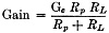 , where Gc is the conversion conductance, Rp is the plate
resistance, and RL is the tuned load resistance. Published values
of plate resistance and conversion conductance can therefore be used to calculate
conversion gain. The tabulation following gives a comparison of gain for a group
of tubes now generally available. The gain figures were calculated for a tuned
load impedance of 200,000 ohms, which is equivalent to the better transformers
now available. , where Gc is the conversion conductance, Rp is the plate
resistance, and RL is the tuned load resistance. Published values
of plate resistance and conversion conductance can therefore be used to calculate
conversion gain. The tabulation following gives a comparison of gain for a group
of tubes now generally available. The gain figures were calculated for a tuned
load impedance of 200,000 ohms, which is equivalent to the better transformers
now available.
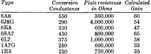
Tube Parameters
If gain was the only consideration the above would suffice for the selection
of a converter tube. Tube noise is generally not a consideration when comparing
converters simply because the converter is inherently a noisy device and most
converters develop noise voltages of approximately the same magnitude. The noise
output of converters of the 6A8 and 6SA7 type is approximately 4 times greater
than that of an r.f. amplifier like the 6SK7 or 6K7. Where the ultimate in signal-to-noise
ratio is desired it is necessary to precede converters of this type with an
r.f. stage. Usually the selection of a converter is based on the characteristics
of oscillator stability with regard to a.v.c. and terminal voltage fluctuation,
pull-in characteristics, oscillator transconductance that determines the ease
of oscillation especially at high frequencies, and other deleterious characteristics
that cause loss in performance at certain frequencies. The chart on page 41
indicates some of the characteristics of the various converters. The gain figures
and notes on stability and oscillator transconductance are of particular importance.
What's the best mixer tube? How can a mixer circuit be tested to find out if
it's doing the best job it can? Here are the answers - plus design information
of highly practical value.
In general the converters perform equally well as mixers or as converters
with the exception of the one characteristic of oscillator stability. Any of
the converter tubes gives good stability if used with a separate oscillator
and the circuits are isolated properly. Of the group the 6SA7 makes the best
mixer because it gives high gain and has improved internal shielding of the
signal and oscillator grids. The improved shielding is accomplished by using
shielding plates similar to the beam-forming plates used in beam power tubes.
These plates are attached to the side rods of the screen grid and confine the
electron currents to beams which get into the outer regions of the tube where
they are modulated by the signal grid. The sketch of Fig. 1 shows the construction
of the 6SA7. The side rods of the No.3 or signal grid are mounted so that they
split the' beam and make the electrons travel in radial paths. Electrons turned
back by the signal grid because of a strong r.f. voltage do not return to the
oscillator or No. 1 grid because they are caught by the collector plates. This
reduces coupling between the signal and oscillator grids and improves stability.
Simple structures of cylindrical grids such as used in the 6L7 and 6A8 do not
have this additional isolation and are therefore not quite as good as the 6SA7.
The improvement in stability evidences itself in the form of greater freedom
from "pull-in " - that is, shifting of the oscillator frequency with signal-grid
tuning or with a strong signal on the signal grid. This effect is usually not
as serious as frequency shift due to terminal voltage fluctuation. The remarks
relative to stability, given in the tabulation on page 41, refer to the stability
with regard to terminal-voltage fluctuation.
Converter Circuits
[borders/_temp/2-28-2024/google-300x250-ad-unit-included-file-left.htm]Typical circuits for the six converters listed in the tabulation are shown
in Figs. 2 to 7 inclusive. The 1A7G, 1R5, 6K8, 6A8, and 6SA7 can be used with
separate oscillators simply by connecting the oscillator grid of the converter
to the oscillator grid of the oscillator tube. The screen and other positive
electrodes should be maintained at their normal rated d.c. voltages but should
be by-passed to ground.
Fig. 2 shows connections for a converter circuit using the 1A7G and
Fig. 3 shows connections for the 1R5. The 1R5 is one of the new miniature
tubes for hearing aids and small portable receivers. The 1A7G has the conventional
6A8 construction, using an anode for feedback. The chart above indicates that
the gain obtainable with either tube is approximately 34. The oscillator transconductance
of the 1R5 is slightly higher and the oscillator stability is somewhat better.
These two features are of advantage for high frequencies.
Figs. 4, 5, 6 and 7 show connections for converter circuits with types 6A8,
6K8, 6J8G and 6SA7 respectively. The high oscillator transconductances of the
6K8 and 6SA7 make them particularly suited for all-around usage. They oscillate
strongly at high frequencies where Lie ratios are unfavorable. The 6A8 construction
is not satisfactory for amateur usage because of instability in the oscillator.
The oscillator electrode is a pair of rods located in the tube between the No.1
grid and the screen. These side rods collect electrons from the cathode stream
and the electrode current is controlled by the No.1 grid. Unfortunately, changes
in signal-grid or screen voltage also change the anode current. This conductance
between signal grid and oscillator causes instability with variation in a.v.c,
voltage. Fluctuations in screen voltage due to supply regulation also change
the frequency. As a result, the 6A8 is subject to motorboating or "put-put"
at high frequencies. Dial calibrations also drift with line voltage fluctuations.
"Pull-in" is particularly bad with the 6A8.
The 6J8G construction incorporates a triode oscillator and a mixer section
with a common cathode. This construction results in good stability insofar as
screen and a.v.c. voltages are concerned. The 6J8G has two serious disadvantages,
however, that have limited its application. The triode section shares a portion
of the cathode area. The area used by the triode is quite small and as a result
the oscillator transconductance cannot be made high. Also, at high frequencies
a peculiar effect is experienced that causes a flow of current to the signal
grid. This current causes a high negative potential across the resistance in
the grid return, and this bias reduces the gain of the mixer. The effect can
be reduced somewhat by using a high value of screen voltage, but it is then
necessary to increase the bias to hold the cathode current to a safe value.
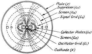
Fig. 1 - Diagram of the 6SA7 structure, showing electron
beams.
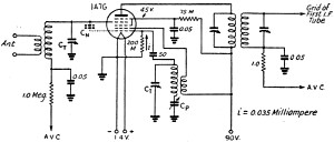
Fig. 2 - Converter circuit for the 1A7G or 1A7GT.
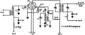
Fig. 3 - The 1R5 converter circuit.
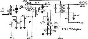
Fig. 4 - Converter circuit for use with the 6A8. 6A8G
or 6A8GT.
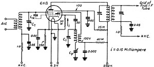
Fig. 5 - The 6K8, 6K8G or 6K8GT converter.
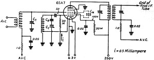
Fig. 6 - Converter circuit for the 6J8G.
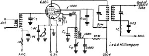
Fig. 7 - The 6SA 7 converter circuit.
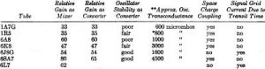
* Circuits using both plate and screen current for feedback can be employed
and the effective transconductance is then 1200 micromhos.
** Transconductance in micromhos at rated conditions. Note - Gain figures
are relative for a tuned load resistance of 200,000 ohms.
The 6K8 has been used extensively by the amateur and also the commercial manufacturer
principally because it gives fair stability, and design problems are usually
simple. The tuned-grid oscillator shown in Fig. 5 gives very little trouble
and is easy to build. The oscillator frequency is not independent of screen
and .v.c. voltages, but in most designs the frequency shift caused by one is
offset by the other so that good stability is obtained. The 6K8 has an effect
known as space-charge coupling which is experienced at high frequencies. This
effect is as follows: The oscillator voltage on the No.1 grid causes a fluctuation
in the number of electrons in the region of the signal grid. The electron density
changes at the oscillator frequency and as a result a displacement current flows
into the signal grid. At high frequencies where the signal grid and oscillator
frequencies are quite close, the impedance of the signal grid circuit at the
oscillator frequency is quite high and as a result the displacement current
produces an a.c. voltage across the signal grid circuit. This voltage, when
smaller than the bias, reduces the gain of the tube slightly. Under extreme
conditions it overrides the bias and causes rectification in the signal-grid
circuit, causing a serious loss in gain. The coupling can be neutralized by
a small capacitance - approximately 2 or 3 μμfd - between oscillator and signal
grids. Commercial practice is to use a condenser (known as a "gimmick") made
by wrapping two pieces of wire together to give the desired capacitance. Neutralizing
the space charge increases the gain and image ratio.
The 6SA7 construction has already been described. Using cathode feedback
in the Hartley circuit shown in Fig. 7, excellent stability is obtained.
The gain is quite high and the high oscillator transconductance makes a good
oscillator.
The 6SA7 converter is tricky to use because the cathode returns through the
oscillator coil. This connection, however, is the secret of the stability resulting
with the 6SA7. The feedback is obtained from the total cathode current. A.v.c.
voltage variations on the signal grid do not change the cathode current appreciably
so that the oscillator frequency is almost independent of a.v.c. Screen-voltage
variation produces a shift in frequency in the opposite direction and the two
effects practically cancel. The frequency change with either variable is reduced
by using the optimum tap on the oscillator coil. With average oscillator coils
the tap should be adjusted to give a total oscillator voltage of approximately
10 volts grid-to-ground. Under these conditions the oscillator grid current
measured in the grid leak will be approximately 0.5 milliampere. This current
can be measured with a 0 to 1 milliammeter by connecting it at the bottom of
the grid leak.
At high frequencies it is necessary to keep the leads connecting the cathode
to the coil, and the bottom of the coil to ground, as short as possible. The
cathode lead in particular should be short. The inductance of this lead is not
a part of the oscillator tank and oscillator voltage developed across it does
not contribute to feedback. The voltage does bias the signal grid, however,
and will reduce the gain of the converter. Under extreme conditions the voltage
may be high enough to cause a flow of current in the signal-grid circuit. This
current results because of high voltage between cathode and ground and because
of phase shift of this voltage with respect to the voltage between grid and
cathode on the coil. The cathode connection to the coil should also be made
so that the lead pulls away from the coil at right angles. By pulling the wire
away parallel to the winding the cathode-lead inductance may cancel a portion
of the tap-to-ground inductance.
In band switching arrangements the circuit of Fig. 8 is recommended.
It will be noted that the tap switch on the oscillator coil is located at the
ground end of the coil. This puts the inductance of the switch and its connecting
leads within the closed tank circuit. Since the tank currents flow through this
inductance it contributes to feed-back and gives oscillation with a minimum
of cathode-to-ground voltage. If the switch was between the cathode and the
coil in the position of lead 1 the drop across the switch inductance would not
contribute to oscillation, but would produce a high cathode-to-ground voltage.
As mentioned above, this voltage is shifted in phase from the voltage in the
tapped portion of the coil and may cause the signal grid to be driven positive
and cause rectification.
The circuit of Fig. 9 shows the 6SA7 as a mixer. It will be noted that
the neutralizing condenser Cn. is used to neutralize the space charge.
The 6SA7 as a mixer gives an increase in gain over that realized as a converter.
Space-charge coupling is also experienced with the 6SA7, and a "gimmick"
is required for neutralization. This coupling is characteristic of converter
or mixer systems wherein the oscillator voltage is injected next to the cathode
or filament. The 6J8G, although not having this coupling, has the transit-time
effect which is just as bad and cannot be neutralized. The transit time effect
is experienced with converters or mixers in which the oscillator voltage is
mixed in the cathode stream outside of the signal-grid injection.
It might be of interest at this point to give the accepted theory on what
causes the transit time effect. Electrons accelerated through the No.2 screen
grid approach the No. 3 injector grid. At high frequencies, where the time of
transit between cathode and No.3 grid is an appreciable portion of the period
of oscillation, electrons accelerated by the No.3 grid on its positive swings
reach the grid at a time when it is going negative and are repelled and turned
back toward the screen. On the way back they are accelerated by the positive
potential on the screen and by the increasing negative potential of the No.3
grid. Many of these returning electrons reach the screen and are drawn off as
additional screen current. Some of the electrons, however, pass very close to
the screen and are accelerated toward the No. 1 grid at high velocity; many
of them obtain sufficient energy to overcome the negative potential of the No.
1 grid and flow in the external No. 1 grid circuit. This flow of current is
d.c., and in a direction such that the drop in the external resistance increases
the bias. If the tube is operated from the a.v.c. string as in the conventional
case, the total return to ground is of the order of two megohms. A current of
several microamperes increases the bias sufficiently to cause an appreciable
loss in gain. The current can be eliminated for frequencies up to approximately
eighteen megacycles by increasing the bias and the screen voltage.
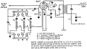
Fig. 8 - Recommended oscillator switching for the 6SA7.
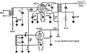
Fig. 9 - The 6SA7 mixer, separately excited by a 6J5
or 6J5G oscillator.
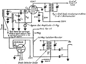
Fig. 10 - Circuit for making performance tests on the
6SA7 converter.
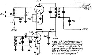
Fig. 11 - Triode mixer with separate oscillator.
Checking Performance
The above information should be useful in determining the converter to be
used for a particular job. Once the converter is built it is comparatively easy
to ascertain whether performance is satisfactory. Of course in the laboratory
the most satisfactory method is to check stage gain with a signal generator,
but few of us have signal generators with which to make precision measurements.
We usually rely on the sound of the set and whether it pulls in the signals.
The first check on any converter is to measure the electrode voltages with
a high-resistance meter. The correct voltages are indicated for the various
circuits. Next in order of importance is to check to see if the oscillator amplitude
is high enough. The easiest method of checking this is to measure the d.c. grid
current in the grid leak. This grid current increases directly with oscillator
voltage and is so closely related to oscillator voltage that manufacturers,
instead of rating the oscillator voltage to be used with a converter, rate the
grid current as measured in a recommended grid leak. On each of the preceding
circuits the rated oscillator grid current is given. In practice the grid current
cannot be held to this value over the band, especially if a wide tuning range
is desired as in commercial broadcast sets. In communications receivers where
the tuning range is small the variation is not large. A 2-to-1 variation in
a set having a wide tuning range is not bad. If rated grid current is obtained
in the middle of the band the variation over the band is usually not excessive.
The grid current is important because it determines the point of optimum gain,
and other than rated value results in a sacrifice in performance.
Converters using the 6A8, 6K8, 6SA7, 1A7G, or IR5 should next be neutralized
for space charge coupling. This is accomplished by connecting a "gimmick" between
the oscillator and signal grids. If a gang condenser is used and the oscillator
and signal grid sections are adjacent, neutralization can be accomplished by
connecting the "gimmick" between the stators of the two sections. Commercial
practice is to solder two small pieces of wire to the stator lugs and then to
twist the ends together. About two turns is satisfactory. Note: Neutralization
is done on the high-frequency edge of the highest-frequency band. Low-loss wire
should be used. The capacitance should be adjusted to give maximum sensitivity.
There are several phenomena that can take place that will upset performance
after the above considerations have been observed. Parasitic oscillations take
place in the oscillator section if too much feedback is used or if the values
of grid coupling condenser and grid leak are too high. A 50-μμfd grid condenser
is usually satisfactory for most circuits. Most grid-leak specifications call
for 50,000 ohms. Battery tubes having low oscillator mutual are specified with
as high as 200,000 ohms, and the 6SA7 with its high oscillator mutual or transconductance
is rated with 20,000 ohms. If the oscillator and signal-grid circuits are not
adequately shielded and isolated, severe coupling between circuits is obtained
at some frequencies. The signal-grid circuit in extreme cases may load the oscillator
enough to cause it to stop oscillating. This effect can be detected by observing
the oscillator grid current as the set is tuned through the coupling point.
A rapid dip in the oscillator grid current is experienced as the coupling point
is passed. Shielding of coils and isolation of parts and leads eliminates this
trouble. Motorboating on strong signals is the result of oscillator shift with
a.v.c. and other element voltage variation. It was pointed out that the 6A8
was particularly bad in this respect, that the 6K8 was much better, and that
the 6J8G and·6SA7 are very good. Motorboating can be experienced with the 6J8G
and 6SA7 if power-supply regulation is bad and if the oscillator amplitude is
not adequate. Stability is improved by operating at or somewhat over rated amplitude.
The major troubles experienced with converters produce a flow of grid current
in the signal-grid return. This is true of the transit time effect with the
6J8G, the space charge effect with 6K8, 6SA7, 6K8, 1A7G and 1R5, and the phase
shift of the high cathode to ground voltage in the 6SA7. The circuit of Fig. 10
shows how a check for signal-grid current can be made without the use of a sensitive
microammeter. An electron-ray indicator tube such as the 6U5/6G5 will indicate
any current flow in the a.v.c. return. Most returns have about three megohms
total and a d.c. current of 1 microampere will produce 3 volts, which will make
a noticeable deflection on the target. The voltage drop between the bottom end
of the coil and ground should never exceed approximately 1.5 volts. This voltage
can exist because of contact potential in the diode and other grids connected
to the a.v.c. system, and does not indicate trouble.
Signal grid current with the 6A8, 6K8, and 1A7G usually results from space-charge
coupling, as already described. A convenient test for its presence is to short
the signal-grid tuned circuit with a condenser. This shorts out the voltage
and eliminates the current. 'The "gimmick" when adjusted properly neutralizes
space charge coupling.
Signal-grid current because of space-charge coupling is also obtained with
the 6SA7 but in addition current can flow because of high cathode-to-ground
voltage and phase shift of this voltage with respect to the oscillator grid-to-cathode
voltage. If bypassing the signal grid does not eliminate the current, the trouble
will be found in the oscillator coil and connecting leads. The cathode lead
should be kept short and the circuit of Fig. 8 adhered to. The ratio of
length to diameter of the oscillator coil should not exceed more than about
1.5 to 1. With long coils and small diameters there is appreciable phase shift
with attendant troubles. As mentioned previously the cathode lead should pull
away from the coil at right angles so that it does not couple to the coil.
Recently, certain manufacturers have used triodes for mixers. A typical circuit
for this type of mixer is shown in Fig. 11. It will be recognized as similar
to many of the circuits used in the older days. In commenting on this circuit
it might be said that the chief advantage of the triode is that it develops
very little noise. It is thus possible to add extra gain behind the converter
in the i.f. and get high sensitivity with a good signal-to-noise ratio. The
triode in this connection has serious disadvantages, however. It is necessary
to use a special low-impedance primary i.f. transformer so that the grid-to-plate
capacitance of the triode will not cause loading of the signal-grid circuit.
In the practical case the tuning condenser required to tune the i.f. primary
is approximately 2000 μμfd. The high cathode-to-grid capacitance causes severe
coupling of the oscillator and signal-grid circuits. This evidences itself in
the form of instability with a.v.c. variation, "pull-in " on strong signals,
and oscillator shift with tuning of the signal grid circuit. In applications
where stability is not of prime importance a pentode such as the 6SJ7 or 6AB7/
1853 could be used to give good signal-to-noise ratio. The low signal-grid-to-plate
capacitance in these types would allow the use of conventional i.f. transformers.
* Ken-Rad Tube & Lamp Corporation, Owensboro, Kentucky.
1 - In common terminology, a "converter" is a tube performing the dual functions
of mixer and oscillator; a "mixer" does not incorporate an oscillator section.
Any converter tube can be used as a plain mixer by providing excitation from
a separate oscillator tube. - ED.
Posted September 4, 2023
(updated from original post on 6/16/2011
|


