|
July 1953 QST
 Table of Contents Table of Contents
Wax nostalgic about and learn from the history of early electronics. See articles
from
QST, published December 1915 - present (visit ARRL
for info). All copyrights hereby acknowledged.
|
In this 1953 QST magazine
article, Authors Cohen and Hessinger warn about the
need to consider the capacitive loading effects of shielded and closely-space test
leads when measuring other than direct current or very low audio or line frequencies.
Lead capacitance is especially likely to affect measured values when the frequency
is high and/or the source and load impedances are high. As was common in the day,
capacitance units of μμfd (micro-micro farads = 10-6
x 10-6 = 10-12 F) are cited, which is equivalent to
units of pF (10-12 F).
One Problem in Choosing Test Leads
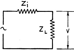
Fig. 1 - The electrical circuit of any generator with an
internal impedance Zi working into a load ZL. A typical example
is a vacuum tube, where Zi becomes the plate resistance and ZL
the load impedance.
By George S. Cohen,* W8HTI, and Richard W. Hessinger*
Every audio enthusiast, amateur radio operator, and electronic technician finds
it necessary at one time or another to make some sort of electrical measurement.
Many of these measurements involve d.c. Bully for the man who has only this type
of measurement to make. But there are those of us who are not quite so fortunate,
for we must make many measurements on a.c. equipment. (This "a.c. equipment" means
anything other than d.c., and so involves a.f. and r.f. as well as commercial power
frequencies.)
All of these measurements require some type of connecting leads from the energy
source to the measuring instrument. In the course of making many measurements it
was found that a source of difficulty, in one instance, was in finding satisfactory
leads for the particular job at hand. Although the measurements of current and voltage
present similar, if not identical problems, we will consider voltage only.
Let us consider the generator of Fig. 1 with an internal impedance Zi.
This source is feeding a load with an impedance equal to ZL. This circuit
is very general and, as an aid in visualizing the problem, the generator may be
thought of as a voltage-amplifier stage in an audio amplifier where Zi
is the plate resistance of the tube and ZL is the impedance the tube
is working into.
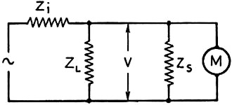
Fig. 2 - Any practical voltmeter can be represented by the
meter M and Zi the impedance of the meter and its leads. Unless Zi
is considerably higher than ZL, the indicated voltage will be lower than
V.
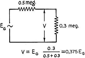
Fig. 3 - When Zi and ZL have the values
indicated, V = 0.375 EG.
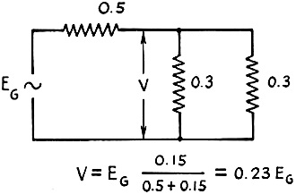
Fig. 4 - If ZS is equal to ZL, the
indicated value of V will be 0.23 EG.
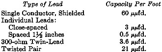
Table I - Capacitance/foot of cables.
If we assume that the generator is a pentode voltage amplifier and that Zi
is, therefore, of the order of 0.5 megohm and that ZL is in the vicinity
of 0.3 megohm, we will have a specific value of voltage, V, across the load.
If Zs is all capacitive reactance, as in this case, it will combine with a resistive
ZL of 0.3 megohm to give a resultant 0.21 megohm and not the 0.15 megohm
shown in Fig. 4.
Now, as is often required, let us measure the voltage across the load impedance
ZL. This circuit is-shown in Fig. 2. M is the meter or measuring
instrument and ZS is the combined impedance of the instrument and its
attached leads.
The voltage V that is measured in Fig. 2 will be approximately equal to
V of Fig. 1 only if the impedance ZS is ten or more times greater
than ZL. This happens because the shunting effect of the impedance, ZS,
combines in parallel with ZL to give a lower resultant value.
As an example, let us suppose that ZS is equal to ZL -
0.3 megohm in this case. The parallel combination of ZS and ZL
would then be equal to 0.15 megohm. Fig. 3 shows that under the original conditions
V would be 0.375 times the generated voltage, EG. With the effect of
ZS the voltage across the combination would drop to 0.23 times EG,
as in Fig. 4. The difference in voltage is made up by additional drop across
the plate resistance of the tube.
Further, if this amplifier were operating at 2 kc. (a reasonable frequency within
the range of most audio amplifiers) then the shunt capacity necessary to give ZS
a value of 0.3 megohm would be 265 μμfd.1
A value of 265 μμfd. may seem very large and unlikely to be found in an
ordinary pair of test leads. Recently, in testing a circuit, we found that our calculations
and actual results didn't agree very closely and that started the usual search.
The culprit was soon found. A shielded multi-conductor cable exhibited a capacity
of 225 μμfd. from leads to shield and 128 μμfd. between leads. After
this discovery, many leads in the laboratory were measured. One of these was a 4
1/2-foot shielded test lead supplied with an oscilloscope made by a well-known manufacturer.
The lead measured 220 μμfd. between shield and the center conductor. A compilation
of the capacities measured between other types of leads is recorded in Table I.
An examination of Table I shows that the experimenter must use good judgment in
choosing an instrument lead for voltage measurement.
There is a second consideration in choosing a lead and that is noise pick-up
of the cable. But we will not enlarge on this subject here.
There are, obviously, many more types of leads than are listed in Table 1. The
manufacturers of these usually list the capacity per foot of each of the different
types and other characteristics that should be considered in using these cables.
We can do no more than point out one of the pitfalls and hope that it has, or
will at some later date, save you from excessive blood pressure and loss of a few
precious hairs.
* Commonwealth Engineering Co. of Ohio, 1771 Springfield St., Dayton, Ohio.
1 
Posted July 8, 2022
(updated from original post on 5/9/2016)
|