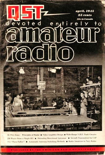
April 1945 QST
 Table
of Contents Table
of Contents
Wax nostalgic about and learn from the history of early electronics. See articles
from
QST, published December 1915 - present (visit ARRL
for info). All copyrights hereby acknowledged.
|
"The prospective peacetime applications of
radar are beyond prediction. Among the more obvious are those relating to navigational
aids and collision prevention. In some of these uses it will be a case of radar
replacing radio." That was 78 years ago when real-world radar was still in its infancy
that futurists were prognosticating on potential uses for radar beyond its use for
the war effort. Just a month after this April issue of QST magazine was published, the war
in Europe ended (V-E Day, May 8, 1945), and four months after that the war in Japan
ended (V-J Day, August 14, 1945).
Editor DeSoto would be utterly amazed at just how widespread radar is today.
It not only surveys the airways for commercial, military, and civilian craft, but
also for marine and land traffic, orbiting spacecraft, and planetary science. Law
enforcement uses it to add to the department coffers, automated landing systems
and security systems depend on it. The list of applications is almost endless.
Radar Techniques
Fig. 1 - To establish the location of the target in space,
three quantities must be determined: distance (range), bearing (azimuth), and altitude
(elevation).
I - Primer Principles
By Clinton B. DeSoto, W1CBD (Editor, QST)
EVERY American - adult or adolescent - astute enough to keep up with the adventures
of Buck Rogers, Smilin' Jack, and Terry and the Pirates is well aware of the existence
of radar - and probably of its operating principles, as well.
He has been told that radar is "a radio wave with an echo" - that a radar beam
is a sharply focused radio searchlight which searches out any object coming within
range of its "owl-like eye."
Whether it be considered as an "eye" or as an "echo," assuredly radar is a means
for projecting the range of human senses far beyond their normal limitations. There
is logic in the thought that, as sound radio is to the ear and television to the
eye, so radar - even though it employs other sensory organs - may be regarded as
an extension of the sense of touch.
The word radar, by official account, was coined from the initial letters of the
prosaic phrase "radio detection and ranging." As a military weapon, radar is utilized
both defensively and in attack. Defensively, it performs the duty, first, of detecting
a trespassing enemy and, second, establishing his precise location. In its offensive
role radar scouts out the prey of pilots of interceptor fighters and the commanders
of naval patrol craft; it aims antiaircraft artillery and the big guns of the battlewagons;
it controls devices which automatically align searchlights, navigate air and seacraft,
and perform many other functions.
The purpose of this series is to discuss the techniques employed in radar, within
the limits circumscribed by military restrictions - to explain radar systems in
general, to present diagrams and simple circuits illustrating the derivation of
the generic units, and to suggest elementary methods employed to achieve the required
effects.
Admittedly, to the thousands of radio amateurs directly associated with this
new art (many of whom, incidentally, have made major contributions to its development)
there will be little we can say that will be novel or useful. Even to those who,
while not directly engaged in radar work, have access to the literature on modem
technical trends, these articles will in all likelihood have 1000 50 only incidental
interest.
There remains, however, the many stay-at-home civilian hams (and also some of
those in military service) who do not have access to such specialized technical
information, and it is for their benefit that this series is written. For them we
shall endeavor to interpret the broader aspects of the technique and evolution of
the art. Moreover, to ensure comprehension even by the neophyte, the explanations
will go back to the underlying principles. Thus this initial discussion concerns
itself only with a generalized summary -a "primer class" treatment of the subject.
Details of component units and certain aspects of the theory involved will be dealt
with in somewhat more detail in subsequent installments.

Fig. 2 - Time intervals for return of reflected signals.
Radio Location
Military radar systems must be capable of (1) searching an assigned area, which
may range from the relatively small frontal-fire arc of a night-fighter interceptor
pursuit to the entire expanse of horizon surrounding a warship or a long-range bomber,
and (2) supplying data for the accurate (and, preferably, automatic) determination
of the quantities necessary to give an exact "fix" on enemy air or seacraft: (a)
direction or bearing (azimuth); (b) altitude (elevation), and (c) distance (range),
as shown in Fig. 1.
The prospective peacetime applications of radar are beyond prediction. Among
the more obvious are those relating to navigational aids and collision prevention.
In some of these uses it will be a case of radar replacing radio. Radar d/f is distinguishable
from familiar radio direction-finding practice by an invaluable quality, described
thus by Dr. Smith-Rose: "An intrinsic feature of the art is that no cooperation
whatsoever is required of the object being detected ... The latter, be it an aeroplane,
ship, building or human being, is merely required to reflect or scatter some of
the radiation which reaches it. ... The detected object is thus merely a source
of secondary radiation which results from its being illuminated, as it were, by
the incident radiation from the primary sending station."
Ordinary radio d/f requires that the object of the search transmit a signal so
that a bearing can be taken. If the mobile transmitter aboard the ship or aircraft
fails, or radio silence is imperative or an enemy bomber fails to "cooperate" and
does no transmitting - well, then no radio bearing can be taken. Radar systems,
however, require of the wanderer only that he serve as a reflector - a form of assistance
which not only can be, but in wartime usually is, rendered involuntarily.
Apart from that significant difference, the two methods are essentially similar.
The procedure in taking a radar bearing may be simply that of rotating a directive
antenna for maximum response in either the horizontal or vertical plane, and then
reading the angle of azimuth or elevation on a calibrated scale to establish direction.
The third item of information required to establish the exact location of a target,
as shown in Fig. 1, is the distance to the object. Here radar displays another
unique quality - its ability to measure the distance to any object in the field
of its beam, like a searchlight with a coupled range-finder, without triangulation.
Modus Operandi
This ability is predicated on three technical factors which characterize radar:
(1) radiating energy in extremely short pulses spaced by comparatively long quiescent
intervals; (2) concentrating the radiated energy in a very sharp (highly directive)
beam; and (3) utilizing electronic devices, which can register and measure split-microsecond
intervals precisely, to determine the transit time of reflected pulses or "echoes."
Because the velocity of propagation or "speed" of a radio wave is constant in
space, and very nearly so in air, the time taken by a pulse in traveling any given
distance represents an accurate measure of that distance.
The process may be described as akin to sending a messenger out into space, traveling
at a known rate of speed, and therefore requiring a given time to reach a given
point and return. The radar messenger is a pulse of r.f, energy; its speed is approximately
the same as the velocity of light; and the time. required to make the round trip
over any given distance and back is shown in Fig. 2.

Fig. 3 - Block diagram of a simple radar system.
Fig. 4 - Timing (direct pulse) and target (reflected pulse)
"pips" on the cathode-ray tube indicator screen.
A typical arrangement for the measurement of distance or range by means of reflected
pulses is illustrated in block diagram form in Fig. 3. Although bearing only
slight resemblance to current practice, it illustrates the mechanics of radar in
readily comprehensible fashion.
Modulated by the pulse generator the radar transmitter radiates short pulses
of r.f. The inter-val between individual pulses is made somewhat greater than the
total time required for the wave to travel to a reflecting target at maximum range
and back to the receiver.
The transmitting antenna emits radiation beamed in the approximate direction
to be explored. Whenever this radiation strikes a surface having characteristics
of electrical conductivity or dielectric constant appreciably different from those
of air, some of the energy will be reflected or scattered back towards the receiver.
While the power radiated from the transmitting antenna is concentrated principally
in the beam reducing the local field to a minimum, the direct radiation is sufficient
to energize the receiver. If the distance between transmitter and receiver is small,
transmission of this direct wave, indicated by the dash line in Fig. 3, is
practically instantaneous. The direct radiation from the transmitter therefore establishes
the starting time of the exploring pulse.
Both direct and reflected pulses are picked up by the receiving antenna and generate
corresponding pulses of signal voltage in the receiver input circuit. After being
amplified and rectified both signals are applied to the vertical deflecting plates
(Y axis) of the cathode-ray tube indicator. There the pulses register on the screen
as vertical deflections of the horizontal timing trace.
The appearance of the screen is shown in Fig. 4. By comparing the distance
between the direct and the reflected pulse indications on the screen, using a known
time base, the distance traveled by the reflected wave can be read on a calibrated
scale. The horizontal (X axis) deflection is synchronized with the transmitted pulses,
giving a known horizontal time base which is adjusted so that the direct pulse indication
coincides with 0 on the scale.
The vertical amplitude of the pulse deflection or "pip" is, of course, proportional
to the relative amplitude of the received signal. Thus the height of the trace tends
to vary with distance, and may also serve to indicate, to some extent, the size
or composition of the target. Moreover, if the target under observation is moving,
the change in its relative position will be indicated by a movement of the pip along
the base line.
Timing the Radio Echo
It is evident that the accuracy of such measurement will be greatly dependent
upon the accuracy of the scale calibration - which, in turn, is dependent upon the
accuracy of the timing base.
The key to the entire system is the pulse generator, which times each and every
step in the operating sequence. For this reason the pulse source must be capable
of delivering a continuous series of precisely identical pulses at an exact and
unvarying repetition rate.
These control pulses synchronize both the transmitter-modulator and the receiver-indicator
functions. Each pulse going in the transmitter direction is applied to the modulator
input and serves to release r.f, power from the transmitter for a period precisely
equal to the duration of the pulse. Similarly, in the receiver direction each pulse
triggers a sawtooth sweep-voltage generator which supplies the horizontal time base
for the cathode-ray tube indicator. Since the resulting sweep frequency is identical
to the pulse repetition rate, the cathode-ray beam makes exactly one traverse of
the screen along the X axis in the interval between each transmitted pulse.
Fig. 5 - Formation of the horizontal timing and vertical
pulse deflections on the cathode-ray tube screen, using a linear (sawtooth) sweep
circuit for the time base.
The cathode-ray tube is comparable to a split-second stop watch, in which the
"sweep hand" makes a complete revolution in terms of thousandths of a second and
reads time in microseconds (millionths of a second). What this means can best be
appreciated by pointing out that, if an ordinary 12-hour clock were speeded up to
a com-parable rate, the hour hand would be making several revolutions per second
rather than two per day.
Obviously, only an electronic instrument can meet such an exacting requirement.
The cathode-ray tube therefore is used to measure the time interval as a function
of voltage. As explained above, the distance or range is then found by translating
that quantity into a function of time.
Cathode-Ray Tube Indicator
At the risk of emphasizing the obvious, let us take a backward glance at some
fundamentals of cathode-ray tube operation.
A cathode-ray tube, as has been explained in so many places at so many times,
is in effect a two-dimensional voltmeter with an essentially weightless, massless,
inertialess pointer. This pointer is a sharply focused electron beam which impresses
its transient indication on the fluorescent material of the screen, creating a luminous
spot wherever it strikes. Normally centered on the screen, the spot from the cathode-ray
beam will be deflected. moving up or down, left or right, in instantaneous response
to the influence of an external electric or a magnetic field. In so moving it leaves
a visible line or trace. Because of the inherent retentivity of the fluorescent
screen and the persistence of vision of the human eye, this luminous trail will
remain visible for 0.1 second or longer.
That, of course, is the principle of the cathode-ray oscilloscope. By translating
any dynamic quantity - electrical or mechanical - into voltage, its characteristics
can be reproduced as a visual image on the screen of the oscilloscope. And that
is just what is done in the radar indicator; the required quantities - time, distance,
bearing, etc. - are translated into corresponding voltages which trace characteristic
patterns on the cathode-ray tube screen.
To establish the relationship between voltage and time, the external circuits
are so arranged as to apply to one pair of deflection electrodes (usually the horizontal
or X axis) a voltage which increases linearly over a predetermined interval of time.
At the end of this interval it will "fly back" rapidly to zero, and then repeat
its relatively slow linear traverse across the screen. This action is pictured in
Fig. 5, where the vertical (Y axis) deflection voltage depicts three received
pulses.
If the linear movement of the beam as it is visually apparent on the screen
is directly proportional to the amplitude of the deflection volt-ages, the screen
may be calibrated rectilinearly in terms of voltage. Thus, with a linear time base,
a rectilinear-coordinate scale can be obtained.
Fig. 6 - Use of a polar-coordinate time base multiplies
the effective scale length by a factor of 3 or more.
It must be understood that the total length of the horizontal base line bears
no relationship to the time scale; it is controlled solely by the peak value of
the sweep voltage. Nor is the amplitude of this voltage related to the time interval;
it serves only to establish the length of the trace. Regardless of the numerical
length of the trace, its proportional parts will always bear the same relationship
to the total time interval. Thus, for a repetition rate of, say, 1000 (0.001 second),
10 percent of the trace will represent 100 microseconds, 5 percent will be 50 microseconds,
etc. - whether the trace itself be 0.5 inch or 5 inches long. Thus any scale may
be arbitrarily divided off into linear units and attached to the cathode-ray-tube
screen; the beam deflection is made to correspond to the scale calibration simply
by adjusting the sweep amplitude to match the scale length.
Provided the time base is perfectly linear, the possible accuracy of measurement
is limited only by the accuracy with which the scale calibration can be read - in
effect, the number of intervals into which the scale can be divided. This, in turn,
is limited by the maximum base length, which obviously must be somewhat less than
the diameter of the cathode-ray tube screen.
A three-fold longer trace and consequent better accuracy can be achieved by using
a polar-coordinate scale. With such a scale the circumference of the screen, not
the diameter, determines the maximum scale length.
To obtain a polar scale, the timing-axis trace must appear as a circle rather
than as a straight line. This requires that a circular sweep be used instead of
a linear sweep. The signal deflection voltage then is applied radially to alter
the shape of the circular trace, causing either a "tooth" or a notch to appear in
the circle, as shown in Fig. 6.
This article is Part I of a series. Part II will appear in the May issue of QST.
(If some kind soul would donate the May 1945 QST, I will post the next installment)
Posted December 15, 2023
(updated from original
post on 2/21/2011)
|