|
November 1952 QST
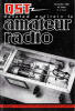 Table of Contents Table of Contents
Wax nostalgic about and learn from the history of early electronics. See articles
from
QST, published December 1915 - present (visit ARRL
for info). All copyrights hereby acknowledged.
|
Even though the concept could easily
be demonstrated to be viable mathematically, single sideband operation was early
on widely regarded as an unrealizable laboratory curiosity, especially with a suppressed
carrier. More circuitry is of course needed to accomplish single sideband communications
both on the transmit and receive sides, but other than stricter stabilities and
precision for frequency sources, single sideband operation is easily obtainable.
Similar to back when this 1952 issue of QST published "The Reception of Single-Sideband Signals,"
there still remains today a debate over whether voice quality is as good versus double
sideband, but there is no arguing whether the spectral efficiency gained with single
sideband is a great benefit to the world. My first experience with single sideband,
suppressed carrier operation was while designing a modem for an Inmarsat base station
installation in Connecticut. At the time, there were no ICs available to do the job, so individual
components were used for the mixers, oscillators, and quadrature power splitters/combiners.
A potentiometer was used on the I channel (in-phase) to null out the carrier. Nowadays,
a single IC does the entire job, including often with an integrated filter, level
adjustment, nulling circuit, and A/D or D/A converter. We've come a long way, baby.
The Reception of Single-Sideband Signals
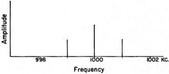
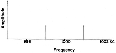
Fig. 1 - The spectrum of a 1-Mc. carrier modulated by a
1000-cycle signal.
Practical Pointers on Two Methods of Operation
By Paul N. Wright, W90HM
According to many remarks heard on the amateur bands, single sideband (s.s.b.)
is a mysterious bunch of gibberish that defies clear reception and causes an unwarranted
amount of QRM. It is human nature to dislike anything not clearly understood. A
problem not readily understood sometimes may be prepared for easy mental digestion
by comparison. It is the purpose of this article to present a comparison of a s.s.b.
'phone signal and an a.m. double-sideband-with-carrier 'phone signal, and to describe
two methods of s.s.b. reception.
Let us first consider the conventional a.m. signal, consisting of a carrier wave
and two sidebands, one on either side of the carrier frequency. We will choose a
carrier frequency of 1 Mc. and a conventional plate-modulated amplifier for our
consideration. We connect a 1-kc. sine wave audio voltage to the input of our speech
amplifier. At the output terminals of the modulated stage, there will appear three
r.f. frequencies: 1000 kc., which is the carrier frequency; 999 kc., the lower sideband;
and 1001 kc., the upper sideband. This is shown in Fig. 1.
In the reception of such a signal, it is necessary to provide a device that is
able to detect the frequency difference between the sidebands and the carrier wave.
This device is the amplitude-modulation detector. The amplitude detector transforms
the frequency difference between the sidebands and the carrier wave into pulsating
d.c. corresponding to the frequency difference, enabling us to recover at the receiving
end the intelligence-bearing frequencies with which we started at the transmitter
end (in this case, 1000 cycles). The frequency-mixing action of the modulated amplifier
provides means for transforming the audio frequencies from the modulator into radio
frequencies approximating the frequency of the carrier. Not only does the carrier
wave provide means for transforming the audio frequencies to radio frequencies in
the form of sidebands; the carrier is also required at the receiving end to produce
the audio beat in the detector. If we were to remove the carrier at the transmitter
and transmit only the two sidebands, the detector in the receiver would detect the
beat between the sidebands instead of the beat between the sidebands and the carrier.
The sidebands being separated from each other by twice the audio frequency will
produce a beat twice the frequency of the original audio tone. This beat coming
out of the detector would then appear as 2000 cycles instead of the original 1000
cycles. (See Fig. 2.)
Fig. 2 - The spectrum of a 1-Mc. carrier modulated by a
1000-cycle signal, with the carrier removed.
Since the only part of an a.m. signal that does not vary in frequency is the
carrier, it becomes readily apparent that the carrier could be replaced at the receiving
end. Only a small fraction of a watt of carrier is required at the receiver, even
on the strongest signal; whereas, to transmit the carrier sometimes requires as
much as 1.5 kw. transformer primary power in an amateur transmitter. Only one sideband
need be transmitted to produce the original audio frequencies at the detector output,
so we can eliminate one or the other of the sidebands. The transmitted signal (or
sideband) will then become simply a carrier (single tone sine wave audio input)
that differs from the original carrier frequency by the frequency of the audio tone.
(See Fig. 3.) A panoramic picture of a double-sideband signal with carrier
and transmitting voice might appear as in Fig. 4A at some instant. An s.s.b.
signal would appear as in Fig. 4B.
The pips or "grass" appearing on the base line of the panoramic pictures in Fig. 4
correspond to the individual frequencies comprising a rather complex voice wave,
with components at 500, 1250 and 2500 cycles.
Bandwidths
All intentional transmission of radio frequency energy is done for the purpose
of conveying thoughts from one place to another. C.w. has enjoyed the No.1 spot
down through the years as the most efficient method of transmission. This efficiency
is obtainable at the receiving end because the unmodulated c.w. signal has no width;
consequently, the selectivity of receivers can be increased many times beyond the
bandwidth required for 'phone transmissions.
The increased selectivity provides a much higher signal-to-noise ratio at the
receiver. The number of c.w. signals that may appear in a given frequency spectrum
without mutual interference is limited only by receiver selectivity, stability,
and effects of keying. Unfortunately, this is not the case with 'phone signals.
In the case of 'phone, the limiting factor is the width of the sidebands produced
by modulation.
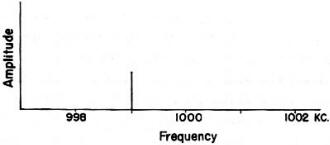
Fig. 3 - The spectrum of a 1-Mc. carrier modulated by a
1000-cycle signal, with the carrier and one sideband removed.
It is generally agreed that an audio bandwidth of 3000 cycles will allow sufficient
fidelity of reproduction for transmission of the human voice. Any reduction below
this figure will tend to reduce the intelligibility of the voice reproduction through
removal of the overtones and sibilant sounds. It would seem, then, that the minimum
bandwidth obtainable with d.s.b. transmission is 6 kc. Referring to Fig. 4B,
we find that only one sideband is required to reproduce the original audio at the
detector terminals in the receiver; so actually the additional sideband may be termed
as excess baggage. It is not needed to reproduce the original modulation at the
receiver. Further, comparing Figs. 4A and 4B, we find that by removing the unwanted
sideband we cut the bandwidth in half. It appears rather obvious that this one stroke
will permit twice as many stations to occupy a given spectrum. It will effectively
double the width of our 'phone hand!
The Carrier
Upon further study of the chart, it would appear that we can improve the over-all
efficiency of our transmitters by eliminating the carrier wave. Since the only intelligence-bearing
energy transmitted is in the sidebands, the carrier does not contribute one bit
at the transmitter end so far as intelligence is concerned. It has served its purpose
of converting the voice modulating frequencies to radio frequencies; there its usefulness
ends. From there on the carrier is excess baggage.
So far as the detector in the receiver is concerned, it isn't particular as to
the source of the carrier. It can just as well be furnished from an oscillator at
the receiving end. If we have succeeded in presenting the thoughts clearly to the
reader up to this point, it will have become apparent that essentially, the s.s.b.
signal is the same as the conventional a.m. signal, with the carrier and one sideband
removed. Therefore, the only thing that needs to be done in order to restore the
original intelligence is to replace the carrier on the signal before it reaches
the audio detector in the receiver.
Reinserting the Carrier
In a superheterodyne receiver, the carrier may be replaced by injecting the carrier
from all oscillator at the i.f. frequency into the. i.f. section of the receiver,
or by injecting the carrier from an oscillator at the signal frequency at the antenna
terminals of the receiver.
If carrier injection from the b.f.o. in the receiver is used, the receiver should
be adjusted as follows: First, with the receiver set up in the regular a.m. position,
tune the bandspread dial for maximum deflection of the S-meter from the s.s.b. signal.
Do not touch the bandspread dial after this. Next, reduce the r.f. gain to zero
and increase the audio gain to maximum. Bring up the r.f. gain until the signal
is heard at a comfortable level; then turn on the b.f.o. and carefully adjust the
frequency of the b.f.o. until the voice sounds natural. If this procedure is followed
closely, little difficulty should be experienced tuning the signal, regardless of
which sideband is being transmitted.
In using the b.f.o. method of carrier insertion, it should be pointed out that
practical reception of s.s.b. signals depend upon the stability of the h.f. oscillator
in the front end of the receiver, as well as the stability of the beat oscillator
that supplies the carrier. Any frequency change in the h.f. oscillator produces
the same effect as changing the frequency of the transmitter on the other end. The
h.f. oscillator in most receivers is fairly stable on the lower frequencies. However,
at frequencies above 5 Mc. the stability of many h.f. oscillators leaves much to
be desired, when thinking in terms of the stability required from these oscillators
when using i.f. carrier insertion.
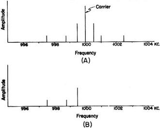
Fig. 4 - A comparison of (A) a 1-Mc. signal modulated by
a complex wave, and (B) the same signal with carrier and one sideband removed.
In using carrier insertion at the signal frequency from an external oscillator,
the procedure is as follows: With the receiver set up in regular a.m. position,
first tune the bandspread dial for maximum indication of the S-meter from the signal.
Then adjust the frequency of the external oscillator to the approximate frequency
of the incoming signal, and increase the amplitude of carrier injection to a point
that approximates the amplitude of the s.s.b. signal. When this point is reached,
the S-meter will no longer swing with modulation. Carefully adjust the frequency
of the external oscillator until the voice sounds natural. Rock the receiver bandspread
dial back and forth across the carrier. You will easily be able to tell which sideband
is being transmitted. As you leave the carrier, on one side the audio will drop
off; as you swing on the other side, the audio will come up. The more selective
the receiver, the more pronounced this effect.
An s.s.b. signal suffers a certain amount of nonlinear distortion when demodulated
by a linear rectifier. The amount of distortion produced is relative to the modulation
depth of the injected carrier by the s.s.b. signal. Increasing the carrier injection
above the 100 per cent modulation point will reduce the nonlinear distortion in
the detector to a negligible amount. Increased carrier also helps swamp out adjacent
channel QRM and generally to improve the signal-to-noise figure.
The advantages of front-end carrier insertion are:
1) Stability of the received signal.
2) S-meter reports may be given on s.s.b.
3) It makes round tables including s.s.b. and a.m. stations practical, since
the receiver remains in the a.m. position at all times.
4) Oscillators in the s.s.b. exciter may be used to furnish the stable carrier
to the receiver, providing consistent "on frequency" operation of the transmitted
signal.
Point 4 is very important from the standpoint of pleasurable operation and good
operating practice of a s.s.b. station. Since the oscillators in the s.s.b. exciter
furnish the carrier to the receiver, the transmitted signal is automatically on
the same frequency as the received signal. This means that only one oscillator has
to be adjusted to get both the receiver and the transmitter on the same frequency.
Of course, any large frequency shift would require resetting of the receiver bandspread
dial. This method, if universally adopted, would make practical operation of single
sideband as simple as operating an a.m. transmitter, by eliminating the extra tuning
procedure. With amateur s.s.b. operation still in its infancy, elimination of a
tuning operation may not seem of much importance. However, as new s.s.b. stations
come on the air and spread out on the bands, the elimination of a tuning operation
becomes more important. If all s.s.b. stations involved in a voice-controlled round
table were using their exciter VFO for carrier insertion to the receiver, they would
remain on the same relative frequency. Using this system, any drift occurring in
the local VFO, or drift occurring in a VFO on the other end, is compensated for
while listening. It would not be necessary to halt the entire round table QSO every
so often and realign on somebody's frequency. Proof of the need for the adoption
of this operational method can be obtained by listening to any large s.s.b. round-table
QSO on 75 meters. Note the confusion and the lost time caused by off-frequency operation.
Then, too, it is rather difficult to impress anyone that single sideband has come
of age and can step in the same ring with a.m. after they listen to that sort of
operation.
There is another advantage to VFO carrier insertion. Those who have used it have
found that when they are in QSO using voice-control break-in operation, they can
control the QRM situation very nicely. If they hear QRM come in on the low side,
they merely move the VFO higher until the QRM disappears. If the QRM comes in on
the high side, they move the VFO down until the interference disappears. With the
tuning ease afforded by this system, rapid QSY is practical, providing a most effective
way to dodge QRM.
Construction of signal-frequency carrier generators will be discussed in a subsequent
article.
Posted January 4, 2023
(updated from original
post on 6/23/2016)
|