|
|||||||||||||
 |
|||||||||||||
Resistance and Capacitance Measurements with the V.T.V.M. |
|||||||||||||
Prior to the advent of FET-input multimeters, obtaining a very high input impedance meter required the use of a vacuum tube circuit that used a buffer stage to isolate the measured signal from the loading effects of the meter movement. As most people reading this article already know, the voltage value indicated by a non-buffered meter can be greatly affected by the meter's loading of the device under test (DUT) if the meter's impedance is not many times greater than the DUT's impedance. The voltmeter is used in parallel with the circuit under test, so for example if the impedance of the DUT is 100 kΩ and the meter's impedance is also 100 kΩ, the meter will display a value as if the DUT itself had only a 50 kΩ impedance, which represents a huge error. The problem was that VTVMs were relatively expensive and beyond the budget of most amateurs. This article from the June 1944 edition of QST presents a simple vacuum tube voltmeter VTVM project that allows the user to measure both resistance and capacitance. Nowadays you can buy a nice quality equivalent with a digital readout for $50 from Craftsman, or dedicated LCR meter for about $35.. Extending the Usefulness of a Versatile Instrument By A. D. Mayo Jr., W4CBD Few garden-variety hams have either the equipment or the inclination to construct elaborate measuring apparatus for checking either condenser capacity or high values of leakage resistance. This article describes a simple and effective way of making such checks by the reactance method, requiring only an all-purpose v.t.v.m. as a non-loading voltmeter. Almost any a.c, vacuum-tube voltmeter can be used to indicate the approximate capacities of small condensers without requiring the addition of extra parts. All that is necessary is to apply the filament-supply voltage to the input terminals of the meter, in series with the condenser, and note the resulting voltmeter reading. The voltmeter can be calibrated in micromicrofarads and a separate graph prepared to make it direct-reading for this use.
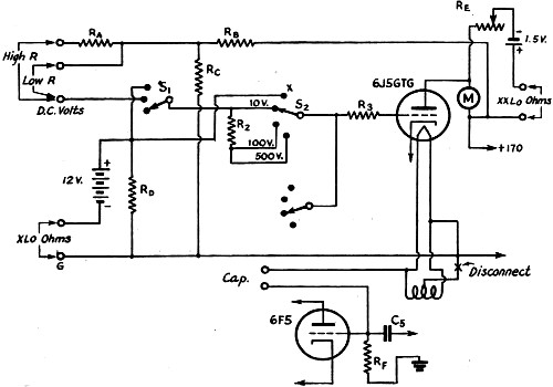
Fig. 1 - Changes in wiring required to convert the author's v.t.v.m, (originally described in November, 1943. QST) into a wide-range instrument for measuring capacity and resistance. RA - 90 megohms. RB -1 megohm. RC - 700,000 ohms. RD - 10,000 ohms. RE - 200-ohm variable. RF - 3 megohms.
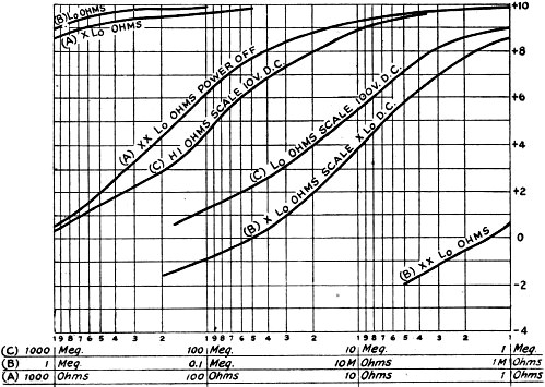
Fig. 2 - Typical resistance calibration curves for the v.t.v.m.
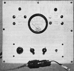
Front view of the v.t.v.m. described in the November issue of QST, as modified with pin jacks added on the panel for making connections for resistance and capacitance measurements.
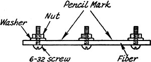
Fig. 3 - Calibrating resistors for extending the range of the v.t.v.m. are constructed by making pencil marks on an insulating strip, as described in the text. This method of checking capacity is similar to that described on page 407 of the 1944 edition of the ARRL Handbook, which shows how an ordinary 1000-ohms-per-volt a.c. meter can be used to check capacities down to 0.001 μfd. The principle is similar to that of the d.c. ohmmeter, except that impedance is measured instead of resistance. The limitation in the use of this method with an ordinary voltmeter lies in the fact that an external source of a.c. is required, as well as a resistor or two and some terminals. Nor does the capacity range extend quite low enough to check small mica condensers. A vacuum-tube voltmeter using a voltmeter tube on extended leads overcomes these objections, since a.c, voltage is available at the tube from the filament supply. With the very high input resistance of the v.t.v.m., the capacity range covered can be extended down to 50 μμfd. or less. The only leads necessary are one to the probe tip and one to the ungrounded side of the filament. When using a 3-megohm input resistor on the probe tube and a filament voltage in the neighborhood of 6 volts r.m.s., capacities of from 50 μμfd. to 0.002 μd. will give an indication on the 10-volt scale. The filament voltage will divide between the input resistance of the meter and the reactance of the unknown condenser. The internal resistance of the small condenser does not affect the reading unless the condenser has high leakage or is otherwise defective. The reactance of a 50-μμfd. condenser at 60 cycles is about 32 megohms. When this reactance is placed in series with the filament supply and the voltmeter input terminals, about one-tenth of the supply voltage will appear across the meter. Practical Application The homemade v.t.v.m. described in the November, 1943, issue of QST1 has been used in this manner for a rough check of small capacities, and it has turned out to be a very handy tool. The changes required in the original circuit may be noted by comparing the diagram of Fig. 1 with that shown in the November article. To use the meter for this purpose it was necessary to change the ground connection from the center-tap of the filament to one side, as shown in the circuit diagram. The voltage at the end of the tube prod was 5.7 volts r.m.s., which gave a reading of 8 volts peak on the meter scale. A separate calibration curve was made for capacity against voltage by taking readings on several condensers which were known to be close to marked capacity. In testing a handful of new and junk-box condensers we noted some surprising readings. Out of about a dozen new mica postage-stamp condensers tested there was one which showed no capacity at all and another which read so high it was tested for d.c. resistance and found to have 10 megohms leakage resistance. Any attempt to use either of these condensers at very high frequencies would probably have led to a long headache before the trouble could have been found. On the other hand, one very old condenser of about 1925 vintage, of the type having mica and brass strips clamped together without any molded Bakelite covering, tested 0.001 μfd. as marked and did not show any abnormal leakage. Resistance Measurement It is apparent that, in order to check a condenser thoroughly, it should be tested for leakage resistance as well as capacity. The v.t.v.m. also lends itself very well to conversion into an ohm-meter for reading extremely high values of resistance. For this purpose the d.c. plate supply is applied to the d.c. voltmeter section through the unknown resistor in much the same manner as that previously described for measuring capacity with the a.c. section. The internal plate-supply voltage of the instrument runs 170 volts above ground. Of this, 100 volts is tapped off on a voltage divider and applied to the 100-volt input terminals in series with the resistance to be measured. This scale reads from 1 megohm to 100 megohms and is called the LO-OHM scale. To read higher values of resistance the 100-volt supply is applied to the 100-volt scale through the unknown resistor, with an additional resistor of 90 megohms added in series to limit the maximum voltage applied across the meter input to 10 volts. This scale is labeled HI-OHMS and it reads from 1 megohm to 1000 megohms. The HI- and LO-OHM scales worked so well that two additional ones were added (XLO and XXLO in Fig. 2). The XLO scale is obtained in a manner similar to that used in the higher resistance ranges, but the input resistance of the meter had to be reduced by connecting in an additional switch point, shunted with a 12,000-ohm resistor, as shown in Fig. 1. Since some current was required to operate this section, a battery was added as the easiest way out. The XXLO scale is made up by using the milliammeter in a regular ohmmeter circuit with another 1 1/2-volt battery. It is important that the power be turned off in the meter before using the latter range, since the meter is in the "B"+ side and is above ground by about 170 volts. Finally, a terminal was added to the panel to supply one side of the filament voltage. In using the 1000-megohm range it is important to keep down leakage in the test prod leads if they are used. The leakage through many insulators will be less than 1000 megohms. Newsprint paper on a damp day will show a reading if the prods are pressed on it a couple of inches apart. It is best to use a couple of bare wires pushed in the HI-OHM terminals with the condenser connected to them as close to the terminals as possible. Calibration It turned out to be fairly easy to calibrate the meter at the high ranges. Perhaps the accuracy of the method used is less than that obtained on the best commercial bridges, but it is sufficient for our purpose. In constructing the calibrating resistors, a piece of fiber was drilled with three holes in a row and machine screws and washers put in the holes, as shown in Fig. 3. Pencil lines were drawn from under the washers on to the next screw, making a pair of 1920-model pencil grid leaks in series. A 10-megohm resistor was obtained and one of the grid-leak sections adjusted to the same resistance as measured by the meter scale. Then the other grid-leak section was adjusted to the same resistance. Since the total resistance of both grid-leak sections is 20 megohms, the meter deflection for 20 megohms was recorded. Then each section was made 20 megohms, making a total of 40 megohms. Thus, by doubling resistance each time, the calibration was carried on up to 1200 megohms. The resistances were adjusted by marking on a little pencil lead or erasing a little of it until the resistance was correct. The meter was calibrated at the lower ranges by plotting points from resistors which were measured by another ohmmeter of good accuracy. The original meter as shown in November QST did not have a case, but after its conversion to read ohms and whatnot it was mounted in a wooden case and some additional terminals put on the panel, as shown in the photograph. It was a case of something that started out to be a voltmeter and ended up being a meter to read nearly everything else as well. For something that was born on the kitchen table from parts out of the junk box, this thing turned out to be a good little instrument.
1: Mayo. "A V.T. Voltmeter for A.C. and D.C .," QST, November. 1943. p. 36.
Posted November 5, 2020 |
|||||||||||||
 |
|||||||||||||
|
|||||||||||||


|
||||||||||||||||||||||||||||||||||||


