|
November 1966 QST
 Table of Contents Table of Contents
Wax nostalgic about and learn from the history of early electronics. See articles
from
QST, published December 1915 - present (visit ARRL
for info). All copyrights hereby acknowledged.
|
Mr. Wilfred Jensby wrote an incredibly
detailed article for the November 1966 edition of QST that delves deeply
into the subject of using transmission lines as distributed circuit elements. I
did a search on his name, figuring that he likely had other publications of like
sort, but nothing was found. Information contained herein is similar to what you
would expect to find in a Master's level engineering course textbook or in a $100+
technical book from Artech House, Cambridge University Press, John Wiley & Sons,
etc. The brain-zapping equations are omitted with only a great, layman-level discussion
of the concepts and some really nice illustrations and graphs. This is definitely
an article you will want to check out and pass on to colleagues.
A Review of Transmission Lines as Circuit Elements
By Wilfred Jensby, WA6BQO
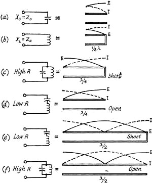
Fig. 1 - Table of equivalent circuits using resonant lines.
Voltage and current relationships are illustrated for open and shorted line.
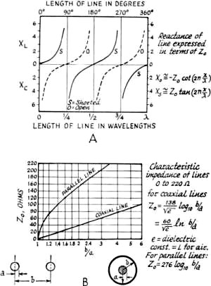
Fig. 2 - Chart showing reactance of lines, expressed in
terms of Z0, is illustrated at A. At B, a chart showing the characteristic
impedance of lines from 0-220 ohms.

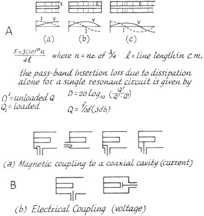
Fig. 3 - Approximate voltage and current distribution in
one-quarter wavelength (A), one-half wavelength (B), and three-quarter wavelength
(C) resonant coaxial lines. The field strength, E, is also shown. At B, an illustration
of magnetic and electrical coupling to coaxial cavity circuits.
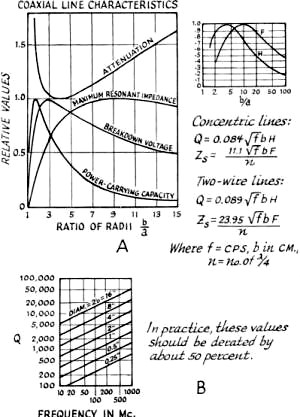
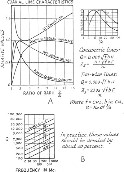
Fig. 4 - Graphic representations of coaxial line characteristics
are shown at A. At B, a chart showing Q in connection with element diameters and
frequency, for concentric lines based on b/a = 3.6, using copper lines and air dielectric.
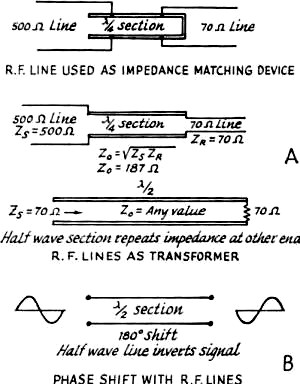
Fig. 5 - Illustrations of various applications for parallel
line sections as discussed in the text, at A. Phase-shift characteristics for line
sections are shown at B.
Many amateurs active on the v.h.f. bands enjoy building their own equipment. The
r.f. circuits often consist of hardware or plumbing which involves considerable
metal work. Cut-and-try methods involve much more time and expense than at the lower
frequencies.
I will review some of the design details involved in high-frequency circuit construction,
so that most of the cut-and-try work can be done on paper.
Transmission-line sections are used as circuit elements at v.h.f. because of
their desirable impedance properties. Lines that are used for such purposes are
usually open-circuited or short-circuited at the receiving end, and do not serve
to actually transmit energy. The term" transmission line" is used for purposes of
clarity.
Equivalent Circuits
If we consider only what appears at the input terminals, a short-circuited quarter-wavelength
line and a parallel-resonant circuit, of coil and capacitor, have these characteristics
in common; both present extremely high impedance at one particular frequency; with
both, the impedance at resonance is resistive and the impedance drops rapidly if
the frequency varies slightly from resonance. Both will carry direct current freely
while effectively blocking the frequency to which they are resonant.
An inherent difference is that the transmission line displays similar resonance
at all odd multiples of its lowest resonant frequency; and has the inverse resonance
characteristics of a shorted half-wavelength line at the even multiples.
An open-circuited quarter-wavelength line is similar to a series-resonant circuit
of coil and capacitor. It has extremely low impedance at the resonant frequency,
is resistive at resonance while being inductive above and capacitive below this
frequency. It blocks direct current while freely passing the resonant-frequency
r.f. energy. Like a short-circuited line (but unlike a circuit of lumped constants),
its characteristics tend to repeat at odd multiples of the lowest resonant frequency,
whereas at even multiples the inverse characteristics appear.
An open-circuited half-wavelength line is similar to a short-circuited quarter-wavelength
line in that both have the same Q and are thus equally selective in a resonant circuit.
However, at radio frequencies other than the desired resonant frequency (such as
half and double the fundamental resonant frequency), the open and short-circuited
lines have quite different characteristics. This may be important in connection
with harmonics.
'With a quarter-wave line, the closest resonant frequencies to the fundamental
occur at odd multiples such as 3, 5 and 7 times the fundamental frequency. With
a half-wave line, they occur at multiples of 2, 3 and 4 times the fundamental. A
quarter-wave resonant line, therefore, gives greater separation of the higher-resonant
frequencies from the fundamental.
Parallel Lines
Parallel lines are most often used with push-pull circuits, in either quarter-wave
or half-wave configuration. With half-wavelength lines, the B plus is connected
at the electrical center of the lines, and often a coil, resonant at a lower frequency,
is placed here to give multiband operation.
Parallel lines are relatively easy to construct. Their electrical length may
be readily changed with short-circuiting bars, and when they are used with appropriate
types of tubes, the connections between lines and tube terminals can be short and
direct. Furthermore, these connections and the portions of the tube leads inside
the envelope become parts of the resonant-line system. For very high frequencies,
the tube leads may constitute the principal part of this system but are largely
inaccessible for purposes of power-output coupling. In some cases, the portion of
the circuit from which power is to be coupled may be operated at a multiple length
of the shortest possible line; e.g., three-quarter rather than one-quarter wavelength.
Since open parallel lines radiate electromagnetic energy when excited, it is
necessary to shield these lines for optimum performance. The parts, such as sides
and covers, of the metal boxes used as the shield should be well bonded together,
either with screws or by contact fingers. This is because electromagnetic shielding
depends on the flow of induced currents in the metal of the shield. For the same
reason, the shield should be constructed from material of high conductivity. For
ultra-high frequencies, silver plating is desirable.
Several methods of tuning are available. An adjustable short-circuiting strap
can be used, which must make good electrical contact. If the line is also short-circuited
at the end by a large disk of copper or other good conducting material, it will
be more effective. A butterfly capacitor, or a parallel-plate capacitor, may be
placed anywhere along the line the tuning effect becoming less pronounced as the
capacitor is located nearer the shorted end of the line.
The characteristic impedance of parallel conductors may be calculated as follows:
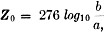
where b is the center-to-center spacing of the conductor and a is the radius
of the conductors. This relationship is shown in Fig. 2.
For two-wire lines, minimum attenuation theoretically will occur when b/a = 2.7.
However, when proximity effect is included, the optimum b/a ratio is about 4. The
b/a ratio to give maximum impedance to a short-circuited quarter-wavelength 2-wire
line i about 8.0.
Coaxial Lines
When the various characteristics (Fig. 4) of a coaxial transmission line
are considered, such as attenuation, resonant impedance, breakdown voltage, and
power-carrying capacity, an optimum ratio of b/a = 3.6 is found to exist, where
b is the inner radius of the outer conductor, and a is the outer radius of the inner
conductor. Minimum attenuation occurs at this value, which also corresponds to a
characteristic impedance of 77 ohms for a line with air dielectric. This is an important
reason for the widespread practical use of lines with approximately this impedance.
Physically, if the inner conductor is smaller than the optimum size, its resistance
is higher and loss is increased. If the inner conductor is larger than optimum,
the increased capacitance lowers the value of Z and hence more current is required
to transmit a certain amount of power, with the result that loss is again increased.
However, a line designed for minimum at-tenuation is not best for all purposes.
A line may be designed to transmit maximum power. The limiting factor is electric
field strength at the surface of the inner conductor; if a critical value of field
strength (about 30,000 volts per centimeter) is exceeded, corona or sparking results.
The optimum value of b/a for maximum power transmission is 1.65, and the corresponding
characteristic impedance is 30 ohms.
When a line is designed to act as a resonant circuit, other values of b/a may
be preferred. For a short-circuited resonant coaxial line to have maximum impedance,
b/a should be 9.2, corresponding to Z0 equals 133 ohms for an air-insulated
line. For an open-circuited resonant line to have minimum impedance, the inner conductor
of the coaxial line should be as large as possible, requiring Z0 to approach
zero.
Coaxial-Line Oscillators and Amplifiers
The adoption of conventional oscillator and amplifier circuits to u.h.f. use
is facilitated by the use of coaxial lines as circuit elements. The high inherent
Q of concentric lines as resonant circuits, the very low radiation, and the possibility
of isolation of the circuits, contribute to successful design. The lighthouse tube
is designed especially for such circuits. The cylindrical, or dish construction,
is carried through from the external terminal of the tube to the active part of
the tube elements. A high degree of circuit isolation is thus possible, and coupling
between circuits is reduced to a minimum.
The grounded-grid circuit is often used for oscillators and amplifiers at u.h.f.
and is particularly advantageous in amplifier operation. The feedback or coupling
capacitance between output and input circuits is the plate-cathode capacitance,
which is reduced to a minimum in most tubes suitable for coaxial circuit use. Thus,
regeneration through interelectrode feedback is materially reduced by grid shielding.
The similarity between the grid-separation-type oscillator and amplifier circuits
is considerable. The conversion of an oscillator to an amplifier consists primarily
of removing the external feedback system, the addition of a source of driving energy,
and retuning. The plate-circuit loaded Q will influence both the frequency stability
and modulated bandwidth of an oscillator and, for a given loaded resonant impedance,
will depend on line dimensions, tube capacitance, and the operating mode.
Loaded-Q Consideration
Whereas in the ideal case, the expression for the input impedance of the coaxial
line is frequently treated as a pure reactance, it should not be forgotten that
the line is actually a circuit element with distributed constants, both inductive
and capacitive. While the inductive reactance of a short-circuited line less than
90 degrees in length may be used to tune out a terminating capacitive reactance,
the total capacitance in the resonant circuit is materially increased by that which
is distributed in the line.
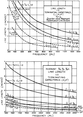
Fig. 6 - Nomograph for determining physical lengths of lines
at various frequencies with relation to terminating capacitance.
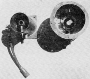
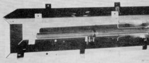
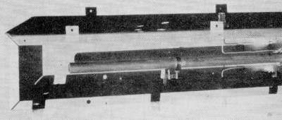
Fig.7 - A photo of a typical 432-Mc. amplifier coaxial cavity
(upper), and a 432-Mc. coaxial filter, with crystal diode detector added (lower).

Fig. 8 - A block diagram illustrating three typical applications
for coaxial filters.
The distributed capacitance of a coaxial line is a function of the characteristic
impedance. This is of importance where high operating Q must be considered for its
limitation on the modulated bandwidth or, in the case of an oscillator, for its
influence on frequency stability. A given input reactance might be obtained with
a short high-characteristic-impedance line or a long low-characteristic-impedance
line. The resonant circuit Q of the short line when shunt-loaded with a given resistance
will be lower than that of the longer line if the electrical length of the lines
is less than 90 degrees. The extra storage of energy in the low-impedance line will
increase its operating Q over that of the high-impedance line. Where physical dimensions
are concerned, low and high might be considered to be about 20 and 90 ohms, respectively.
Limitations on Tuning Range
A practical limitation on the low-frequency range of a coaxial oscillator or
amplifier is the actual physical length of the line elements, which rapidly increases
as the frequency is lowered. This can be appreciated when the actual physical quarter-wavelength
is considered at low frequencies, for the resonant lines approach this length quite
closely as the reactance of a fixed terminating capacitance increases with the decrease
in frequency.
When over-all physical length is an important consideration, it is helpful to
remember that a given terminating capacitance may be resonated, with a fixed-maximum
length of line, to a lower frequency with a line of higher characteristic impedance.
Physical dimensions also influence the practicable upper-frequency limit of coaxial
lines as resonant circuit elements. This results from the ability of cavities of
large radial electrical dimensions to support interfering waveguide and spurious
coaxial-resonance modes. The principal interfering higher-order coaxial-resonance
mode is the TE mode, which can exist only at wavelengths less than the cutoff value
given by:

where a is the radius of the inner conductor, and b the radius of the outer conductor.
In any event, this TE mode should not interfere if the resonant-circuit line lengths
are less than 90 degrees.
Coaxial Filters
Preselectors, or bandpass filters, are often made using quarter-wave or three-quarter-wave
coaxial resonators. These can be nearly identical to coaxial v.h.f. amplifiers except
that they are passive circuits. A preselector is a device used to pass discrete
bands of frequencies within a limited operating range, while rejecting signals at
frequencies outside its passband. It can be very useful in suppressing transmitter
harmonics and in reducing receiver overloading due to strong signals outside the
amateur v.h.f. bands.
When designing a filter, it is necessary to know the minimum passband attenuation
and bandwidth desired. If it is made tunable, then the filter can be adjusted for
minimum loss at any particular frequency. Nearly all the characteristics of a coaxial
filter can be related to Qu and QL where Qu is
the unloaded Q of the filter, and QL is the loaded Q of the filter. The
unloaded Q of a cavity depends on the frequency and the impedance and size of the
cavity. The theoretical Qu of a coaxial cavity can be obtained from the
equation
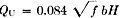
where b is in centimeters, ƒ is in c.p.s. and H a factor related to b/a
as shown in Fig. 4, at A. The Q of resonant coaxial lines of optimum proportions
(b/a = 3.6) is shown in Fig. 4, at B. Usually, these values must be derated
from 10 to 50 percent because of lower conductivity than predicted, contact resistance
between movable and fixed parts of a cavity, capacitive loading effects of coupling
elements and end plates, and other unavoidable imperfections.
Losses in coaxial filters are of two kinds - mismatch and dissipation. If the
filter is simply inserted in a 50- or 70-ohm line, a good match can be obtained
if the input and output loops have the same size and shape and are located at points
of equal intensity. Usually, the effect of self-inductance of the coupling loops
is merely to shift the resonant frequency slightly.
Dissipation (or resistive)
loss is an important factor in narrow-band filters because of the relatively high
values of QL required for narrow passbands.
The passband insertion loss, due to dissipation alone, for a single resonant
circuit is given by
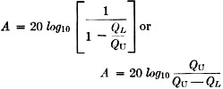
where A is the dissipative loss in db. To have an insertion loss of less than
1 db., Qu must equal 10 QL.
The Q of a resonant circuit may also be defined as the ratio of the mean passband
frequency to the 3-db. bandwidth F/ƒ or

A v.h.f. coaxial filter showing input and output coupling lines. The tuning capacitor
is tapped down on the resonant element.
Since selectivity and insertion loss are directly related to QL, both
functions can be adjusted for any particular need by making the coupling variable
(such as rotatable loops).
If two or more cavities are used in series to increase the selectivity, they
should be spaced an electrical one-quarter wavelength from center to center.
The position of the loops, with respect to the center conductor of the cavity,
also has an effect on QL. The closer the coupling the lower the QL
and the greater the bandwidth.
In practice, a certain amount of electrical coupling will be combined with the
magnetic coupling of the loop, depending on the size of the loop.
As an example, a coaxial filter for two meters might be designed to cover the
entire band of 4 megacycles. Thus,
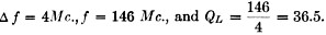
To keep the insertion loss A below 1 db., Qu should be 365. From Fig. 4B,
a coaxial cavity of 1/2-inch outer diameter has a theoretical Q of about 600. Usually,
more selectivity than this is desired, and a previous article listed typical cavity
dimensions for the various v.h.f. bands.
A filter such as this can be made tunable either by changing the length of the
inner conductor or by capacitive loading. The latter is generally less difficult
to accomplish.
"The World Above 50 Mc.," QST. February, 1961.
Additional Considerations
The best method in constructing transmitters, converters or filters using resonant
line elements is to follow the ideas in articles in the handbooks and magazines.
A typical circuit for parallel-line construction is the 2-meter transmitter described
in QST.2 A coaxial-line amplifier for 2 meters is described in an earlier
issue of QST.3
An important consideration, when constructing similar equipment, is to determine
the length of the quarter-wave section of transmission line. The equation used to
solve this problem is
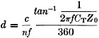
where d = quarter-wave resonant length in inches. c = velocity of propagation
in a vacuum (1.18 X 1010 inches/sec.). n = index of refraction of
the dielectric medium = 1 for air. ƒ = operating frequency in cycles/second.
CT = Terminating capacity in farads. Z0 = Characteristic impedance
in ohms and tan-1 is in degrees.
This equation is illustrated graphically in Fig. 6, relating line length
to terminating ca-pacity for various frequencies. For these curves, Z = 71 ohms
and n = 1.
These curves may be used for resonant lines having a characteristic impedance
other than 71 ohms by using the conversion

where C0 is the terminating capacitance normalized with respect to
the 71-ohm impedance.
To use this chart, determine the total minimum capacitance across the end of
the line, including tube or tubes and tuning capacitor. Find the length of the line
at the highest frequency used. Remember, the line can be lengthened electrically,
or lowered in frequency by adding capacitance, but it can only be shorted electrically
by cutting it off.
Construction Notes
The ideal way to build a coax-line amplifier or coaxial filter would be to use
copper or brass tubing, silver plated on the conducting surfaces, and with all joints
soldered. However, satisfactory results can be obtained with less effort. As an
example, a coaxial filter for use on 6 and 2 meters was constructed, using a 3 X
4 X 17-inch aluminum chassis box and a 13 1/2-inch length of 5/8-inch copper tubing.
If 1-inch diameter tubing is used, a length of 14.12 inches should be about right.
A 2 3/4 X 3 3/4-inch plate was soldered to one end of the tubing and mounted in
the box. Input and output connectors were mounted on opposite sides and about 4
inches up from the base. Wire loops, the shape of an L, were spaced about 1/8 inch
from the center conductor. A 3-30-pf. capacitor was connected halfway up the line.
This provided enough capacitance to tune the line to resonance at 6 meters. The
filter was tried on each band, with a power output of about 40 watts, into a wattmeter
and 50-ohm load. The insertion loss was approximately 1 db. at center frequency.
Spurious emissions and harmonics outside the bands should be suppressed by 40 to
50 db. Birdies and interference from TV and f.m. stations should also be similarly
suppressed. When using a multiband antenna on 6 and 2, a filter such as this should
help to prevent 6-meter third-harmonic energy from being radiated by the 2-meter
section.
References
VHF Techniques. Vols. 1 and 2.
Radio Engineering Handbook, Terman.
Radar Circuit Analysis, USAF.
Lighthouse Tubes," General Electric ETX-110.
Moreno, Microwave Transmission Design Data, Dover Publications, Inc., New York,
N. Y.
"Narrow Band Pre-selectors," Microlab Catalog No. 11A.
Penfield, "Design of Quarter-Wave Resonant Lines," Electrical Design News, June.
1959.
Posted December 28, 2020
(updated from original post on 2/25/2013
|