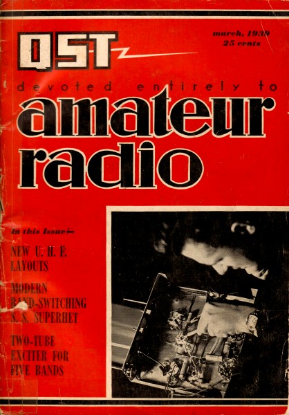
March 1939 QST
 Table
of Contents Table
of Contents
Wax nostalgic about and learn from the history of early electronics. See articles
from
QST, published December 1915 - present (visit ARRL
for info). All copyrights hereby acknowledged.
|
 Special Snowflake alert on this article from a 1939 edition of
QST magazine! Do not read the first paragraph if you are easily offended
or easily induced to self-flagellation over misplaced guilt for statements made
by people you had no relation to or control over. If you are brave and decide to
continue, author George Grammer provides a very good guide regarding how to be safe
around high voltage, high power electronics equipment. A lot of the opportunity
for harm has been removed with modern transistorized circuits and improved chassis
design, but there are still plenty of people who work with vintage and/or homebuilt
equipment and are thereby exposed to potentially (pun intended) dangerous levels.
This note on the
voltage present at the ends of a λ/2 dipole fed with a 1,500 W full limit
power (Ham radio) has 4,397 Vrms or ±6,200 Vpeak - that'll leave an RF burn mark
on 'ya. Special Snowflake alert on this article from a 1939 edition of
QST magazine! Do not read the first paragraph if you are easily offended
or easily induced to self-flagellation over misplaced guilt for statements made
by people you had no relation to or control over. If you are brave and decide to
continue, author George Grammer provides a very good guide regarding how to be safe
around high voltage, high power electronics equipment. A lot of the opportunity
for harm has been removed with modern transistorized circuits and improved chassis
design, but there are still plenty of people who work with vintage and/or homebuilt
equipment and are thereby exposed to potentially (pun intended) dangerous levels.
This note on the
voltage present at the ends of a λ/2 dipole fed with a 1,500 W full limit
power (Ham radio) has 4,397 Vrms or ±6,200 Vpeak - that'll leave an RF burn mark
on 'ya.
Safety Technique in Transmitter Operation and Construction
 Introducing the A.R.R.L. Safety Codes - Study
Them Introducing the A.R.R.L. Safety Codes - Study
Them
By George Grammer,* W1DF
We've been told that the American pioneers once had a saying, "The only good
Indian is a dead Indian." We'd like to paraphrase that slogan and shift the phase
by 180 degrees: "The only good amateur is a live amateur." And then never forget
it when we're working around radio equipment.
Far more amateurs die from natural causes, or from accidents not connected with
radio, than are killed by electrocution in the course of ham operating or experimenting.
That is fortunate. "Fortunate" is exactly the right word, too, because nearly every
amateur can tell of a narrow escape from death or serious injury by electrical shock
- we know, because we've heard of innumerable cases since the untimely deaths of
Ross Hull and Phil Murray. And most hams, having come through such an experience
without serious damage, never realize by what an exceedingly small margin they made
good their escape. With a small change in atmospheric or bodily conditions, or a
slight difference in the layout of equipment or bodily position at the time of contact,
there might have been an entirely different story to tell - with someone else doing
the telling.
We've talked a lot about safety among ourselves here at Headquarters in recent
months. What could be done to make amateurs safety-conscious, to instill in them
a healthy respect for electrical circuits? What should be done to transmitters to
make them more safe to operate and adjust? We spent days in round-table discussions
examining suggestions, contributed by amateurs in the field as well as ourselves,
from all angles to expose their weak as well as strong points. We consulted safety
codes of other organizations in the electrical field. We came to the realization
that much could be done to make equipment, particularly transmitting equipment,
safer, but that, at least at the present stage of the game, no transmitting equipment
could be built that would permit the operator to blindfold himself, stick his hands
in the works with all the power on, and be perfectly safe while doing it. We realized,
too, that a lot of inertia had to be overcome - no one is going to get involved
in constructing safety devices when, after all, he's not going to be guilty of carelessness
in handling dangerous voltages. And so we found that the subject of safety naturally
divided itself into three sections: First, a set of rules for personal conduct in
the handling of transmitters; brief, easily memorized, designed to prevent shock
when operating or adjusting any transmitter. Second, a set of constructional precepts
which, although involving no special hardships or expense, would minimize danger
of shock in normal operating or adjustment; really, a code of good practice in transmitter
construction. Third, special devices such as interlocks, warning signals and the
like, whose purpose is to protect the operator from the disastrous consequences
of a moment of forgetfulness.
Every amateur should make it a point to read this article thoroughly. It summarizes
the results of much individual thinking and many intensive group conferences into
two simply-applied safety codes, one covering precautions that should be taken when
working around transmitters, and the other, methods of making the transmitter itself
less dangerous in ordinary operation. Read them; put them into effect at once!
With so much that can be said and done about safety, we must confine ourselves
to the first two classifications for the present; special safety devices will be
reviewed in a future issue.
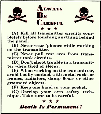
The "personal" code is most important. Its seven simple points should be remembered
as automatically as the characters of the international telegraphic code, and applied
as instinctively. They are displayed prominently elsewhere in this article, but
are so fundamental that they deserve repetition here:
(A) Kill all transmitter circuits completely before touching anything behind
the panel.
If we could be sure this rule would be followed unfailingly by everyone, we could
almost end the discussion right here. After all, no one is ever hurt by a "dead"
circuit. But far-reaching though it is, this rule is not quite enough. Phil Murray,
remember, was handling only a microphone, supposedly as safe a piece of equipment
to touch as anything about a transmitter. When changing coils, making internal adjustments,
or shooting trouble inside the transmitter, kill all the power circuits before handling
anything. If you have to see what happens with the power on, don't close the switch
until after you're clear. Does the risk seem worth the few minutes saved by disregarding
this rule?
(B) Never wear 'phones while working on the transmitter.
Headphone circuits usually work back to ground, and the cord insulation isn't
intended to stand high voltages. When you get a shock, your hand is nearly always
at one end of the circuit; your chances are pretty slim if your head is at the other
end.
(C) Never pull test arcs from transmitter tank circuits.
R.f. may not shock you, but it can cause bad burns. And it can readily travel
through a pencil or screwdriver - possibly to be followed by high-voltage d.c. Like
s.w.l. cards, the arcs may impress the visitors but they don't mean much.
(D) Don't shoot trouble in a transmitter when tired or sleepy.
And, we might add, after a convivial evening. Your reactions are slow, you're
more likely to forget to take normal precautions. Get some rest first.
(E) When working on the transmitter, avoid bodily contact with metal racks or
frames, radiators, damp floors or other grounded objects.
One side of the high-voltage circuit is, or should be, grounded. You don't want
to contact ground with any part of your body while working on some part which may
be at high potential. This is a precaution which, if made a habit, may save you
should you forget "A".
(F) Keep one hand in your pocket.
This can also be made a habit. Its purpose, of course, is to prevent the two
hands from being the opposite terminals of a circuit through the vital parts of
the body.
(G) Develop your own safety technique.
Take time to be careful.
We all develop operating habits which become practically automatic. Make it a
point to develop safety habits, too. You can, for instance, train yourself to open
the main switch without conscious thought every time you push back your chair to
get up from the operating table. Work out a routine for safe operation, practice
it, make it a part of your second nature.
Code for Transmitter Construction
We've conceded that no transmitter can be made completely shock-proof under any
and all conditions. But all transmitters can be constructed so that all operations
such as tuning and switching normally carried on from in front of the panel are
perfectly safe. And much can be done to "safetyize" the inside of the set.
In formulating the construction rules to follow we had a dual idea in mind: First,
to eliminate danger from sources where it should not normally be expected, such
as at front-panel controls. Known "hot" spots in the transmitter are still to be
treated with utmost respect; still, it is possible to make some of them innocuous.
Second, to minimize the danger to life should there be a breakdown somewhere in
the equipment. This seldom-considered point is highly important, as the Murray case
proves. Altogether there are eighteen rules, most of them already in common use
by the more thoughtful constructors, at least. The majority deal with methods rather
than specific equipment, and none of them appreciably raises costs. Those not already
observed in existing transmitters can be applied quite readily, often with but little
inconvenience. The reason, for each one should be obvious, but we'll devote a few
words of explanation to each. Here they are:
(1) Grounds - With chassis construction, all negative terminals of plate-voltage
supplies and positive terminals of bias supplies should be connected to chassis
and to a good ground. Chassis should be connected together and to the rack, frame
or cabinet, if of metal.
With breadboard construction, negative terminals of plate-voltage supplies and
positive terminals of bias supplies should be connected together and to a good ground.
The important thing here is that everything supposed to be at ground potential
actually should be grounded. Then if a transformer or other component breaks down,
no harm can come to the operator from touching a normally "dead" component or structure.
Fuses may blow, and some equipment may be damaged, but such things can be replaced.
Phil Murray would be alive today if there had been an actual ground on the speech
amplifier.
It has been suggested that both sides of power-supply circuits should be insulated
from all metal chassis, the r.f. returns being made to chassis through by-pass condensers.
Thus the chassis and either side of the circuit could be touched simultaneously
without danger of a greater jolt than the discharge from a small by-pass condenser.
But this system gives no protection from defective equipment, and we believe it
better to conform to the standard practice of connecting one side of each supply
circuit (negative in the case of plate supplies and positive in the case of bias
supplies) to the chassis, and then grounding the chassis. Of course, there is no
large metal surface in the usual type of breadboard construction, but the general
principle should be followed just as faithfully.
(2) Control Shafts - All shafts, jack frames and other metal parts protruding
through panels should be grounded, regardless of whether the panel is metal or insulating
material.
For safety in tuning, this rule is extremely important. Obviously, there should
be no possibility of getting "bitten" from a control which one has to handle. Condenser
shafts, in particular, only too often are at the full plate voltage above ground,
and only such insulation as the tuning knob may have protects the operator. Even
though the knob may be good bakelite, there is still a set screw coming too close
to the fingers for comfort. The only safe way is to make the shaft dead, either
by using a circuit which permits grounding the condenser rotor, or by using an extension
shaft to drive the condenser through an insulating coupling. In the latter case
the extension shaft alone is not enough; it should be grounded to the panel, if
metal (the panel in turn being grounded), or directly connected to ground by wire.
Then if the coupling breaks down the only damage is to the plate supply. Extension
shafts and panel bushings are readily obtainable and inexpensive.
(3) Plugs, Jacks and Cords - When plugs and jacks are used for meter switching,
the circuit should be arranged so that the jack frames can be grounded. The plug
cord should be heavily-insulated flexible cable, or shielded cable with the shield
connected to the plug sleeve.
This rule is very commonly disregarded - mostly, it must be admitted, in connection
with supposedly non-dangerous low-voltage circuits. Certainly no jack on the front
panel of a transmitter should be at anything except ground potential; it is only
too easy to touch it accidentally. Practically, this means that the meter jack must
be connected in the negative plate-supply lead or positive bias-supply lead; if
it cannot be connected in this way because a common supply is used for two or more
stages, then some other method of meter switching should be used.
Note that additional precautions should be taken with respect to the cord. This
is not just one of those things to "make assurance doubly sure" but is an essential
part of the rule. Should the meter develop an open circuit, a considerable difference
of potential - possibly depending upon the circumstances, the full plate voltage
- will appear across the wires of the cord. There should be no possibility of insulation
breakdown which might result in a serious shock. The safer of the two alternatives
is to use a shielded cord, with the shield connected to the plug sleeve and thus
automatically to ground, through the jack frame, before the meter circuit is made.
Always
Be
Careful
* * *
(A) Kill all transmitter circuits completely before touching anything behind
the panel.
(B) Never wear 'phones while working on the transmitter.
(C) Never pull test arcs from transmitter tank circuits.
(D) Don't shoot trouble in a transmitter when tired or sleepy.
(E) When working on the transmitter, avoid bodily contact with metal racks or
frames, radiators, damp floors or other grounded objects.
(F) Keep one hand in your pocket.
(G) Develop your own safety technique. Take time to be careful.
* * *
Death Is Permanent!
(4) Cases and Cores - Transformer and choke cores, cases and other metal work
not normally a part of the electrical circuit should be grounded.
This is a measure against equipment failure. Breakdown of a winding to the core
is probably the commonest of transformer and choke failures. Since the core and
case are normally dead such a breakdown can be doubly dangerous, because the appearance
of voltage on them is totally unexpected. Don't take it for granted that the bolts
holding the units to the chassis make a ground connection; test with an ohmmeter
and make sure of both core and case. Units with the core enclosed are best, since
the laminations of the core are usually insulated to some extent to prevent eddy-current
loss.
(5) Master Switch - There should be one power line switch, in a conspicuous and
easily-accessible location on or near the transmitter, which controls all power
to the transmitter,
Without such a switch, the habit of turning off all power before going behind
the panel may be difficult to form. Make it easy to kill the transmitter - you're
more likely to follow the cardinal " A" of the" ABC's."
(6) Power Supply Enclosures - Power sup-plies should be so enclosed or constructed,
or so located, that accidental bodily contact with power circuits is not possible
when adjustments are being made to r.f. or audio units.
A grounded cover over a power supply is the safest type of construction. With
relay racks, the power supplies are usually at the bottom where a leg or knee may
come in contact with exposed wiring when adjustments are being made. Lacking a cover,
the next best thing is to use construction without exposed high-voltage points;
this is covered in some of the following rules. Alternatively, the power supply
may be located well out of reach when work is being done on the transmitter; this
means, however, that it cannot be on the same rack or frame with the transmitter
proper.
(7) Bleeders - A bleeder resistor should be connected across the d.c. output
terminals of each rectified a.c. power supply.
From the electrical design standpoint, every power supply of this type ought
to have a bleeder anyway. As a safety precaution, to discharge filter condensers,
the bleeder is absolutely essential. Filter condensers can store up quite a charge,
particularly on circuits over 1000 volts, and even though the discharge may not
last very long it is not to be lightly dismissed - there may be enough energy available
to be as dangerous as a continuous contact. And a lot of things can happen in the
reaction; the uncontrollable jump you give may result in damage both to yourself
and the apparatus.
Even with a bleeder on the supply, it doesn't pay to take it for granted that
the condensers are discharged when the power goes off. Bleeders can open up with
no warning. Special methods of making sure of the bleeder will be discussed in subsequent
issues.
(8) Resistors - Resistors should be so located or protected that accidental bodily
contact is impossible. When one side of the resistor is open for adjustment, the
resistor should he mounted with the exposed side in such a position that it cannot
he touched. Sliders, when used, should be insulated or protected by barriers.
Tubular resistors, unfortunately, are made with exposed terminals. This is also
true of the slider on the semi-variable type. Equally unfortunately, a resistor
usually has to be mounted in a rather exposed location if it is to dissipate the
power it is rated to carry; for the same reason, it cannot ordinarily be mounted
inside a box. A lattice or cane cover, which would give the necessary protection
and still allow plenty of air circulation, would be a good thing to have. Without
it, install the resistor where it can't be touched unintentionally, or put a grounded
metal barrier, large enough to prevent accidental contact, in front of it.
Don't depend on the coating for insulation - it's there to protect the resistance
wire, not you.
(9) Plate Milliammeters - Plate milliammeters preferably should be connected
in the negative plate-supply lead so that one side of the meter can he grounded.
If this is not possible, the meters should be mounted behind the panel (behind glass
if possible) so that accidental contact is impossible.
This practice will protect the meter as well as the operator. Even bakelite-cased
meters are rated for only 500 volts or so when mounted on a grounded panel. The
danger point on a meter is the reset screw, which is responsible for more than one
shock, and the screw therefore should be kept at ground potential. If the meters
have to be connected in the positive leads, by all means put them where they can't
be touched. An insulating mounting behind a relay-rack panel, with a slot for viewing,
is not hard to rig up, and should always be used when the meters are above ground.
(10) H. V. Leads-High-voltage leads should he a good grade of high-tension wire
insulated for at least two to three times the peak operating voltage.
Insulation should be good enough so that a high-voltage lead can be run along
a grounded chassis or frame without danger of breakdown. Then there will be no danger
to the operator should the wire be accidentally touched. Note that peak operating
voltage is specified - this is at least twice the steady d.c. plate voltage when
the stage is plate-modulated. Automobile high-tension wire, in the better grades,
is inexpensive and amply rated for most amateur plate supplies.
(11) Terminals - Exposed terminals and tube caps should he protected by insulating
coverings. Barriers should be placed over exposed transformer terminal boards.
High-voltage terminals, tube caps and the like are highly dangerous points and,
usually, only too easy to touch unless deliberate care is taken to avoid them. Insulated
caps for tubes have been obtainable for a long time, although not generally used
by amateurs. They cost little and are not troublesome to install.
We need a new type of high-voltage terminal to replace the feed-through insulator
generally used for the purpose. It could be built much along the same lines, but
should have a ceramic cap which screws or otherwise fastens to the body of the insulator
and which covers the actual connection after it is in place. There's an opportunity
here for some manufacturer to bring out a really useful gadget. In the meantime,
a rubber sleeve of the type used with test clips could be slipped on the wire before
fastening, and afterward pulled over the terminal to cover all the metal normally
exposed. It would afford considerable protection.
Likewise, there's room for improvement in transformer terminal boards in the
field of protection from accidental contact. When the transformer is mounted so
that the present type of terminal board is within reach in the normal course of
operating or routine adjustment, it ought to be covered up. This can be done quite
easily by running all the wires through a piece of bakelite the same size as the
terminal board and shoving the bakelite piece up quite close to the terminals. It
will be rather hard to get your fingers in, and you'll probably be reminded to turn
off the power before changing connections.
(12) Layout - In construction of r.f. units, components should be located so
that danger of touching high-voltage circuits during adjustments or coil changing
is minimized.
In other words, don't layout a circuit so that you practically have to put your
hand against the tank condenser or the plate of the tube when you change coils.
Coils which have to be changed always should be on the most accessible part of the
chassis.
(13) Parallel Feed - When design considerations permit its use, parallel feed
to transmitting tubes is recommended for circuits in which coils must be changed
manually.
The dangerous thing about a tank coil is the d.c, voltage - r.f. may cause a
bad burn but is not likely to be fatal. So, if there's no d.c. on the coil your
chances are much better should you forget" A" of the" ABC's." As a matter of fact,
there's a lot of unfounded superstition about parallel feed, dating back to the
days when it was hard to get a good choke. But at the present time suitable chokes
are certainly available for low- and medium-power transmitters, at least when the
set is not intended to cover the whole spectrum. Admittedly, it is asking a lot
of a choke to work on all bands from 5 or 10 to 160. We don't say categorically
that parallel feed must be used; rather, we say that if it can be used in your particular
transmitter, it should be, and the set will be just that much safer to operate.
(14) Series Feed - With series plate feed in the final stage, coupling to the
antenna preferably should be inductive; if direct coupling is used, blocking condensers
amply rated to withstand the peak plate voltage should be installed between the
plate tank circuit and the antenna system.
This hardly needs comment. We certainly don't want the plate voltage to appear
without warning at the feeders or on the antenna. Use good blocking condensers,
not only rated for the peak plate voltage (including modulation) but also to carry
the r.f. current that will have to flow through them.
(15) Breadboards - Breadboard-type transmitters should be provided with panels
to prevent accidental contact with live components when controls are operated. Items
(2) and (3) should be observed with respect to apparatus mounted on or projecting
through the panel.
It is obviously desirable to have a breadboard transmitter arranged so that no
danger spots are waiting for unwary fingers when only normal tuning operations are
being carried on. If you have a breadboard layout, by all means put a panel in front
(wood, predswood or similar materials will do) and then treat the panel just as
though the set were in a rack. Meters can be mounted conveniently at the back of
the breadboard where they are easily visible but well out of reach.
(16) Clips - Adjusting clips on tank coils should be provided with insulating
sleeves. Rubber sleeves over clips used to vary antenna coupling in direct- or capacity-coupled
circuits may prevent a burn or shock should the operator forget to turn off the
power while making adjustments. They're worthwhile protection, inexpensive and can
be installed in a few seconds.
(17) Keys - The arm of the telegraph key should be grounded in every case. In
keying circuits which do not permit a direct ground on the key, a suitably-insulated
relay should always be used. Live parts of the key should be protected from accidental
bodily contact by suitable covers or barriers.
Lots of fellows have had jolts from keys, especially those using center-tap keying.
Always arrange the circuit so that the arm of the key can be connected to an actual
ground. This automatically safetyizes most of the exposed metal parts; the remaining
hot points should be covered over so they can't be touched. It would not be hard
to make a small box of wood or metal to fit over most of the key, leaving only the
operating lever in the open. Manufacturers could help out here, too.
Incidentally, the key symbol that appears in diagrams (including those in the
Handbook) is not to be taken as a literal representation of the method of connecting
the respective sides of the key. Convenience usually dictates which way the key
is drawn, and although we intend to make the picture and practice conform wherever
possible, always remember that in doing the actual wiring the key arm should go
to ground, no matter how it is represented in the diagram.
(18) Relays - Relays should be provided with covers, or installed in such fashion
that accidental closing by mechanical means cannot occur.
A relay is a useful and often indispensable device, but is not always to be trusted.
A power or keying relay mounted in the transmitter often can be turned on unintentionally
if something (a tool, for instance) should drop on it and close the contacts. Therefore
the relay should be so placed in the set that such a contingency cannot occur, or
a cover should be installed for the same purpose.
No protection can be afforded against sticking relay contacts without going into
our third section of the safety problem, special safety devices. We shall do that
later. But Rule 5 of the present series, always remembering" A" of the" ABC's,"
will take care of such a situation.
There they are. As we said before, none of them represents any particular hardship,
either constructionally or on the basis of cost. All have the weight of logic behind
them. Naturally we intend to follow them in our own construction, although freely
admitting that exceptions to some of them can be quoted to us both from past QST's
and Handbooks.
Accidents still can happen, of course, even though all these constructional precautions
are taken; that is why we put primary emphasis on the"ABC's." But following them
will do much to reduce the chances of accident; for safety's sake, put them into
practice at once.
One point brought up by a correspondent deserves mention. Many 110-volt lines
have fuses both in the grounded side and the hot side, and a dangerous condition
can arise should the fuse in the ground side burn out, leaving the other fuse intact.
Such fusing was common practice years ago, but is contrary to the National Electrical
Safety Code. Look over your cellar installation, and check to see if there is a
good ground connection to one side of the circuit or to the center wire of a three-wire
system. If so, and the ground or neutral is fused, bridge the fuse by a good solid
connection using wire of the same size as the rest of the circuit. If you have any
hesitancy about making this change, get your local building inspector to confirm
it.
In closing, we want to repeat here the thought in last month's Editorial. No
voltage, including those in the lower hundreds, can be considered non-dangerous
to life. Handle every circuit with caution - remember that the lowly 110 has more
electrocutions to its credit than any other.
* Technical Editor.
Posted April 4, 2023
(updated from original post
on 10/11/2016)
|