|
March 1940 QST
 Table of Contents Table of Contents
Wax nostalgic about and learn from the history of early electronics. See articles
from
QST, published December 1915 - present (visit ARRL
for info). All copyrights hereby acknowledged.
|
A vertical antenna can have a significant
advantage over a horizontal antenna from a maintenance perspective, since, depending
on how high the antenna is mounted off the ground, the "business end" where electrical
connections are made are more accessible. The configuration shown here would be
difficult to implement if a mast rotator is to be used because of the stabilizing
guy wires on the lower frame. Although it should be possible to achieve the necessary
rigidity without guys by using an aluminum or fiberglass tubing frame rather than
wood, preventing weathervaning in strong winds could prove difficult. A nifty feature
of this "reversible beam" antenna that appeared in a 1940 issue of QST
magazine is that reciprocal directivity is implemented simply by swapping out a
short length of wire between the director and reflector elements.
A Stationary Reversible Beam
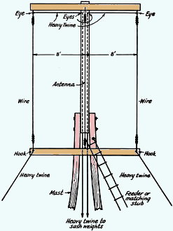
Fig. 1 - A simple uni-directional beam that can be used
for either of two directions. One of the outside wires is changed from director
to reflector by lowering the wire and clipping on an additional length. Lowering
of the wire is facilitated by supporting the elements with heavy twine run through
screw-eyes and counter-balanced by suitable weights. The antenna and feeder remain
fixed under all conditions.
Two Directions with a Fixed Three-Element Vertical Array
By Walter J. Stiles, Jr.,* W8DPY
The beam antenna pictured in Fig. 1 consists of a vertical dipole with reflector
and director. The gain in anyone preferred direction is about 4.5 db, and the lobe
has a vertical angle under 25 degrees. The operator has the choice of either of
two directions by simply pulling up the desired director and reflector. Further,
it can be used as a simple dipole, a great help for local contacts in the evening.
The array is supported on an inverted Y mast consisting of three 18-foot 2 by
4's bolted together with the bottom spread out as a support. Only two guy wires
are necessary if this spread is at least 6 feet, but they can be eliminated if property
conditions allow the mast to be leaned against a garage and bolted tight. A 16-foot
2 by 2 is bolted on top of the tower so that it points along the desired line of
transmission. A small shelf bracket is attached to the top of the mast, to support
the antenna about 6 inches away from the pole.
The operating frequency in the 28-megacycle band is selected, and the length
of the antenna and director wires is computed by the following formulas:
Antenna length = 
Director length = 
One antenna wire and two director wires are cut from No. 14 enameled wire.
A matching section can be constructed from two 8-foot 6-inch pieces of the No.
14 wire spaced by 6-inch spreaders. This section is connected to one end of the
antenna wire as shown in Fig. 1, and the antenna is fastened in place on the
shelf bracket. A 60-foot piece of heavy binding twine is fastened to one end of
each of the directors and this twine is placed through the "eye" hooks as shown.
A sash weight or other object weighing about three to five pounds is then attached
to the end of the twine, and the directors can be pulled in place by simply letting
out twine. You now have a vertical dipole antenna with two directors spaced 1/4
wave from it.
Next compute the length of the reflector from the formula:
Reflector length = 
Subtracting the director length from the reflector length will give the length
of wire to be added to either director to make it serve as a reflector. This done,
cut such a wire and fasten a small battery clip to one end. By lowering one of the
director wires and clipping on the short piece of wire at the lower end, it will
act as a reflector when raised again. If transmission is desired in the opposite
direction, simply lower the reflector wire, remove the lengthening piece, add it
to the other director, and raise the two elements back into place.
Let's consider a specific example: Assuming our operating frequency to be 30
Mc. we find, from the above formulas, the director length to be 14 feet 3.3 inches
and the reflector length 16 feet 2.6 inches. By subtracting the director length
from the reflector length we find the length of the clipping wire to be 1 foot 11.3
inches.
The array also works well on 20 meters and is still well within the space limits
of the average backyard. When used on 20 meters it is sometimes difficult to get
enough height, but the array seems to work well with the bottom only 2 feet from
the ground. Naturally this type of operation is not ideal if the antenna is screened
by trees or houses, but it still out-performs a simple half-wave "Q" strung high
in the air. The same formulas are used to compute element lengths on 14 Mc. - the
spacing is double that of the 28-Mc. array.
The array has also been used in four directions. This was accomplished by using
two 2 by 2 poles at the top of the mast, placed at right angles to each other, and
four director elements instead of two.
One final word to those who might avoid this antenna because they consider inefficient
the short wire used to change a director to a reflector. This wire represents such
a small fraction of the entire length of the element that it can introduce but little,
if any, loss.
Posted September 22, 2021
(updated from original post on 11/9/2015)
|


