|
April 1952 QST
 Table of Contents Table of Contents
Wax nostalgic about and learn from the history of early electronics. See articles
from
QST, published December 1915 - present (visit ARRL
for info). All copyrights hereby acknowledged.
|
We live in days of plenty of everything.
People throw away and stash away items that our parents - and particularly grandparents
- could only dream of having available. Even households that have never seen a penny
of earned income in decades are overflowing with stuff. Shopping carts in Walmart,
K-Mart, and Target are filled to overflowing when I am there with toys, shoes and
clothes, electronic gadgets, sporting goods, automotive accessories, pet food (Target
has reefers with fresh meat for dogs) and accessories, lawn and garden implements,
hand tools, DVDs and Blu-rays, televisions, disposable diapers (lots of disposable
diapers), snack cakes and crackers, soda, bottles of - get this - water (that costs
as much as soda), ice cream, frozen pizzas and microwaveable dinners, energy bars
and bags of candy. You get the picture. People have so much stuff that one of the
largest areas of the store is the plastic storage bin section - reserve one for
each giant, electric fan-inflated Christmas or Halloween lawn ornament. This mid-twentieth-century
tongue-in-cheek anecdote is not so far from how many - maybe most - people lived
at the time.
Stretching the Junk Box
How to Make Use of Leftovers
By Robert G. Seymour, * W9WJS
In this little yarn, W9WJS presents a graphic picture of the problems of a ham
who is low on cash and yet isn't sure just how far he can go in making substitutions
from the junk box. After reading it, perhaps you'll find that you can build that
new piece of gear after all.
 A recent article1 in QST described in some detail the things to be
taken into consideration when building a transmitter. While the information given
was very useful, it did not treat what is often more of a problem to many of us;
that is, how to stretch what we find in the junk box to cut the cost to a minimum. A recent article1 in QST described in some detail the things to be
taken into consideration when building a transmitter. While the information given
was very useful, it did not treat what is often more of a problem to many of us;
that is, how to stretch what we find in the junk box to cut the cost to a minimum.
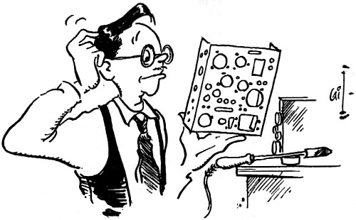
Any transmitter I build is a modification
of some original circuit taken from a handbook or magazine article. Let us consider
the procedure after deciding to build the same transmitter which was described by
Goodman in the original article. We have decided that this rig is the one that will
most closely fit our needs and the one whose parts we most likely have on hand.
We like the idea of including a crystal switch so a look through our stock of switches
reveals that we have one that will do, but it has only three contacts. So, holding
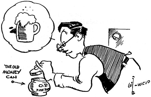
our breath we look in the tin can where we keep our dimes and quarters which we
laughingly call "radio money." Having already looked in the catalogs we find that
the money on hand is enough to cover the cost of a switch, providing no other new
parts are required.
Laying aside the question of the switch for the moment, we go on to the other
parts requirements. Small parts, such as resistors, are already on hand. Of course,
they have been used in numerous other pieces of equipment and the pigtails are a
little short, but that problem can be taken care of by soldering on extensions.
The values may not be just what the circuit calls for, but with a little luck we
can get by with a few substitutions if they are fairly close. For instance, if we
do not have a 47,000-ohm resistor a 56,000-ohmer might do. The only way to find
out is to try it in the circuit. If the circuit calls for a 0.005-μfd. capacitor
and one cannot be found in our stock of parts, a 0.004 will do - we hope. At any
rate we can forget about the small parts until the rig is built and tested, then,
if it does not perform the way the article says it should, we can start to suspect
our substitutions.
Now we compare the larger parts listed for the circuit with what we have in the
junk box. This rig requires two variable capacitors, both 300 μμfd. After
a little searching one is found, but it is only 150 μμfd. However, by winding
the coils properly, this can be used on 80 and 40 meters, which are the two bands
to be used, anyway. But we still need another one. Shall we use the money to get
a variable capacitor and forget about switching crystals? Well, let's wait a while
before deciding and go on to the other parts required.
What other parts do we need? Well, the circuit shows a 150-ma. meter. Now the
only meter that does not already do constant duty is the one in the grid-dipper.
Of course, that one has only a 1-ma. scale, but we could use it by winding a shunt
for it. But now comes another problem. We do not have the coils specified in the
diagram and will have to wind our own, and it will be much easier to wind them if
the grid-dipper is in operation, especially since the capacitor on hand is not of
the value specified. So we will dispense with the meter and use a pilot lamp instead.
We know we are not going to exceed the FCC power limitation with a 6L6 and a pilot
lamp will tell us when the circuit is tuned to resonance and tell us if the antenna
is loading the circuit.
Now the only thing left is a couple of r.f. chokes, and, lo and behold, here
is a brand-new one. Wonder where that came from - must have swapped somebody something
for it. That leaves only one choke that we need. Now let's see - there were a couple
of chokes in that portable rig that was built to take on vacation last summer. Won't
be needing it again until next year and, anyway, if this rig works OK, we can take
it on the trip. So now we get out the destruction tools, a pair of cutters and screwdriver,
and go to work on the portable. What's this? Here is another variable capacitor,
and just what we need. We do not know what the capacitance is but it tuned 80 in
this rig so guess it will work OK in the new one.
We can now go back to the problem of the crystal switch. Everything else has
been taken care of and the money is still in the tin can. Just how advantageous
would it be to have that switch in the circuit? Well, with the switch we can QSY
in a second or two unless we make a big change in frequency. If we do that we would
have to retune the final and antenna tuner which would take - oh, maybe ten seconds.
We could probably change crystals by hand in eight or ten seconds, and another ten
seconds to retune if necessary. Of course, this is assuming that we can find the
crystals, so we would have to make a point of keeping them handy. So, by using the
crystal switch, we can save a maximum of ten seconds or so. Is it worth it? I don't
think so. Besides, we will need a couple of beers while sweating out the actual
construction, and the "radio money" would come in very handy for that purpose.
The Layout
 The next problem is how to fit the parts
in and around the holes already on the chassis we found in the junk box. It would
be nice to start out with a clean chassis, but we are already using parts that have
been used and reused, so why change now? The next problem is how to fit the parts
in and around the holes already on the chassis we found in the junk box. It would
be nice to start out with a clean chassis, but we are already using parts that have
been used and reused, so why change now?
The thing to do is to choose the chassis with the fewest holes, or the one with
the holes most nearly in the proper places. Having done this, we begin. But wait
- how about a panel? Let's look back at the article and see what has to be mounted
on the panel. Just two tuning knobs, a meter and a key jack. Remember, we have decided
not to use a crystal switch, so that will not have to be mounted. We are not using
a meter, so the only things left are the two knobs and the jack. The jack and the
pilot lamp can be mounted on the lip of the chassis, and the knobs can be mounted
directly on the capacitor shafts. So we don't need a panel, and besides, we would
have to do without a couple of beers if we wanted to buy one. No panel.
Now, using the available holes in the chassis, we start laying out the rig in
the way it is to be constructed. Following the accepted practice of making all leads
as short as possible, we can use most of the holes. If a hole does not line up where
we want it, we can punch another one - one more won't make any difference in the
appearance. But we try to use as many of the existing holes as possible because
it saves a lot of work. We want to keep away from making any more large holes because
we would have to borrow a socket punch, which, of course, we do not have.
Because we have used this system of utilizing existing holes, we do not have
to worry much about the placement of the small parts. They will just have to go
in the space available. One thing we must try to do, however, and that is to avoid
placing the parts in more than one layer. The reason for this is that, if when testing
the rig a change has to be made, the parts are much easier to get at if they are
in only one or two layers.
Testing
 Before turning on the power we check our
wiring against the diagram to be sure we have made no mistakes. Remember that we
have made some substitutions and that what may appear to be a mistake in wiring
may not actually be so. Now we plug in the oscillator tube and crystal and turn
on the power. Listen to the receiver on the frequency of the crystal. If we hear
the signal from the oscillator, we plug in the 6L6 and the final tank coil. After
a suitable warm-up we should get an indication on the pilot lamp. But the lamp does
not glow. Well, let's try another 6L6 first. Oh, oh. We don't have another. Well,
temporarily we can swipe the 6F6 out of the receiver. Now everything is fine, except
the pilot lamp will not show a dip in plate current. So now we get out the grid-dipper
and find that the frequency of the tank circuit is too low, so we remove a few turns
from the coil and try it again. Now we get a dip in current and are ready to connect
the antenna. The antenna seems to be loading up properly, so the only thing left
is to check the quality of the signal in the receiver. Before turning on the power we check our
wiring against the diagram to be sure we have made no mistakes. Remember that we
have made some substitutions and that what may appear to be a mistake in wiring
may not actually be so. Now we plug in the oscillator tube and crystal and turn
on the power. Listen to the receiver on the frequency of the crystal. If we hear
the signal from the oscillator, we plug in the 6L6 and the final tank coil. After
a suitable warm-up we should get an indication on the pilot lamp. But the lamp does
not glow. Well, let's try another 6L6 first. Oh, oh. We don't have another. Well,
temporarily we can swipe the 6F6 out of the receiver. Now everything is fine, except
the pilot lamp will not show a dip in plate current. So now we get out the grid-dipper
and find that the frequency of the tank circuit is too low, so we remove a few turns
from the coil and try it again. Now we get a dip in current and are ready to connect
the antenna. The antenna seems to be loading up properly, so the only thing left
is to check the quality of the signal in the receiver.
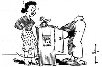
But now the receiver is inoperative because the output tube is being used in
the transmitter. Let's see, the d.c. receiver upstairs has a pair of 6V6s in the
audio, and we could probably borrow one without anyone knowing about it. So we get
one of the 6V6s and put it in the transmitter, return the 6F6 to the receiver and
check the signal. Everything seems to be working fine.
So now we have a new rig ready to try on the air and the beers that we bought
with our "radio money" helped us get through the construction and testing without
too much trouble.
1: Goodman, "How to Lay Out a Transmitter," QST, July, 1951.
Posted June 18, 2024
(updated from original post
on 7/12/2016)
|