September 1967 QST
 Table
of Contents Table
of Contents
Wax nostalgic about and learn from the history of early electronics. See articles
from
QST, published December 1915 - present (visit ARRL
for info). All copyrights hereby acknowledged.
|
This design for a "Swiss Quad" antenna
appeared in the September 1967 edition of QST magazine. One of its touted
strong points is not needing spreaders or a boom. I am not an antenna design guy,
so I can't comment on its usefulness. No gain measurement was provided by the author.
The article states that the antenna had not yet enjoyed widespread adaptation in
the U.S. at the time of the writing. A Google search for Swiss Quad antennas turns
up a handful of modern examples:
IW5EDI, VK4JU,
LU7MGP.
I could not locate an example of a computer-generated gain plot (radiation pattern)
for the Swiss Quad, so if you know where one exists, please let me know so I can
post a hyperlink. Maybe you own a copy of EZNEC and can model it? BTW, the drawings are very well done a
la patent artwork.
The Swiss Quad Antenna at ZS6PP
Rotatable Antenna with Phased Elements
By E.P. Towers, ZS6PP
This antenna, designed originally by HB9CV, has not yet received widespread attention
in the Western Hemisphere. Measurements made by the designer indicate that its performance
is superior to the conventional two-element quad, while the structure is much simpler
and sturdier.
|
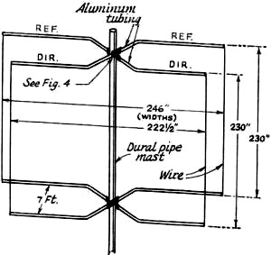
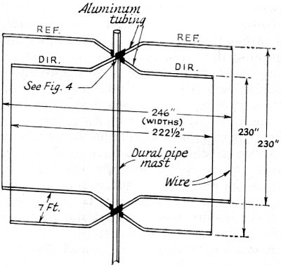
Fig. 1 - The Swiss Quad antenna needs no spreaders or boom.
Dimensions shown here are those used by the author for a center frequency of 14.25
Mc. See Table 1 for suggested dimensions for other frequencies. 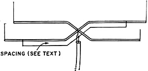
Fig. 2 - Matching system for coax line. The outside conductor
of the line is connected to the ground lug on the lower element bracket. The center
conductor is connected to the center point of the gamma matching section.

Fig. 3 - One satisfactory method of splicing mast sections.
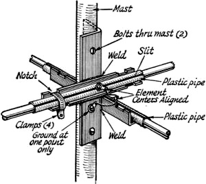
Fig. 4 - Suggested mounting bracket for horizontal sections.
See text regarding insulation.
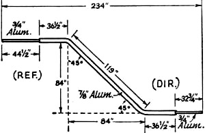
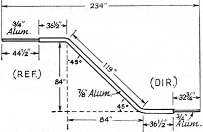
Fig. 5 - All four horizontal members are identical. Dimensions
shown are for a center frequency of 14.25 Mc. Notice that end extensions are not
of equal length. See text for proper orientation in mounting.
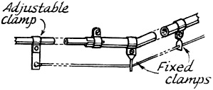
Fig. 6 - Matching sections are made of insulated wire supported
on aluminum clamps attached to horizontal members. Matching sections should be spaced
from antenna elements by about 1/200 wavelength.
Table I
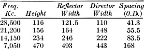
All dimensions are in inches, and are based on a design reflector
perimeter of 1.148 wavelength, and director perimeter of 1.092 wavelength, suggested
as optimum by HB9CV. Width is the overall length of the horizontal members, as indicated
in Fig. 1. Height should be adjusted for antenna resonance at the desired center
operating frequency.
|
In a worldwide survey of 60 DX-minded hams,1 the majority rated the
quad as the "Number One" antenna. However, as we all know, this antenna is more
difficult to construct and erect than a conventional Yagi beam. It is for this reason,
presumably, that it is not in such general use as its reputation would lead us to
expect.
After conducting extensive experiments, HB9CV was so successful in simplifying
the construction and design of the quad that he filed a patent application in 1960
for an entirely new concept of this antenna, and named it the "Swiss Quad."2
Since then, the design of this antenna has been treated in additional articles by
others.3 Reference to this previous material is recommended for full
information.
In constructing a Swiss Quad for 20 meters, the author found that he had to modify
and adapt details suggested by these articles. In response to requests from other
hams around the world for information on his design, these notes from his own experience
and that of others who have constructed similar antennas are presented. Due acknowledgment
is made here to the inventor and to the authors of earlier articles.
Refer to the sketch of Fig. 1 for a general idea of what the Swiss Quad
looks like. It differs from the conventional quad electrically in that both elements
are driven - with a phase difference of 180 degrees. Construction is simplified
by making the horizontal members of aluminum tubing sufficiently rigid to support
the weight of the vertical members, which are made of wire, thereby eliminating
the customary spreaders. Additionally, the horizontal members are bent in such a
manner as to provide the desired element spacing without the need for a boom.
The author's antenna is fed with coax line and gamma match, as shown in Fig. 2.
Supporting Mast
The vertical members are 230 inches long for 14,250 kc. Thus the supporting mast
must be about 20 feet long, plus sufficient length at the bottom for mounting in
a rotator socket or tower bearing. It may also be desirable to add rigidity to the
antenna by extending the mast 2 or 3 feet above the top horizontal members so that
the outer ends of these members can be guyed to the mast with nylon cord. In any
event, it will usually be necessary to splice sections of tubing together to obtain
the necessary mast length. A method of splicing that the author found satisfactory
is illustrated in the sketch of Fig. 3. Sections of 2-inch 10-gauge dural tubing
were used for the mast. Further strength can be added by applying a self-guying
or truss system to the mast. However, the author did not consider this necessary.
Mounting Brackets
The horizontal members are fastened to the mast at the cross-over points by means
of two brackets (one for the top set, and one for the bottom set). The brackets
are made up of three pieces of aluminum or steel angle, as shown in Fig. 4.
An alternative that would avoid welding would be to use wider angle stock which
would provide space for attaching the element-supporting angles individually to
the mast with U bolts and serrated yokes. If this method is used, care must be taken
to make sure that the two angle pieces are oriented at exact right angles to each
other. (The welded arrangement assures this automatically.)
The antenna elements must be insulated from the brackets. To accomplish this,
the author cut sections of flexible 1-inch polyethylene pipe to lengths slightly
longer than the bracket. The pipe was then slit lengthwise so that it could be spread
and forced over the 7/8-inch aluminum tubing of the elements. The angles should
be notched as shown to allow the clamps (gear-type, stainless steel) to secure the
elements firmly. The top bracket can be mounted permanently on the mast before assembling
the antenna. Mounting of the bottom bracket should be postponed until later.
Elements
The sketch of Fig. 5 shows the dimensions of the horizontal antenna members
used by the author for 14,250 kc. All four members are made identical. Forty-five
degree bends are made at equal distances from the centers of a 16-foot length of
7/8-inch 18-gauge aluminum tubing which forms the center section. (Borrow a conduit
bender from your local electrician, or have him do the job; otherwise, the tubing
is sure to kink when the bends are made.) The ends are slit to take extensions of
3/4-inch 16-gauge tubing. The junctions are secured with stainless-steel gear-type
hose clamps. The ends of the extensions should be flattened and drilled for screws
that will be used to fasten the horizontal members and the vertical wire members
together. The extensions are not added until final assembly.
Assembly
The assembly can be started by laying the mast, with upper bracket attached,
across the tops of a pair of stepladders at least 5 ft. high. Clamp the top pair
of horizontal members not too tightly in the bracket while their positions are adjusted
so that the members cross each other at their exact centers. Then twist the members
in the bracket, if necessary, so that they lie in the same plane, at right angles
to the mast. Clamp the members firmly in this position while hole centers are marked
at the exact centers, and in the mast bracket, as shown in Fig. 4. Drill the
holes for sheet-metal screws, attach soldering lugs, line up the members accurately
again, and tighten the clamps. Wire the three lugs together with the shortest possible
leads. Do not allow the leads to touch the bracket at any point. The author found
this precaution necessary to obtain a satisfactory matching adjustment.
The end extensions can now be added, and the telescoping adjusted to give the
widths shown in Fig. 1. The two extensions in each element should be maintained
at equal length, of course. Give all four ends of the horizontal sections a slight
upward bend to help compensate for the weight of the vertical wire members.
The vertical wires can be made of No. 14 copper wire, or stranded wire of equivalent
cross section. No. 8 aluminum TV ground wire is also suitable. If solid wire is
used, stretch the kinks out, and try to avoid reintroducing them during the assembly.
Measure off the vertical lengths shown in Fig. 1. Mark the wires plainly at
the measured length, then add several inches for adjustment. Attach the top ends
of the wires securely to the ends of the top set of horizontal members. Then spray
all connections with acrylic, or apply other suitable protection against corrosion,
or loosening of the securing bolts.
At the center of the clearest available space, drive a section of pipe whose
inside diameter is slightly larger than the outside diameter of the mast into the
ground. Swing the mast vertically and insert the bottom end into the pipe. If an
extension can be added temporarily to the mast to bring the lower horizontal members
at step ladder height above ground, so much the better. (It may be necessary to
guy the mast temporarily with rope.)
Temporarily clamp the bottom mounting bracket to the mast, while the mounting
and adjusting procedure described previously for the upper set of horizontal members
is repeated for the bottom set. Be sure that the longer extensions are on the same
side of the mast as those of the upper set, and that the sets are lined up as accurately
as possible in the same plane. At the conclusion, give the ends a slight downward
bend.
Attach the vertical wires temporarily to the bottom horizontal set at the measured
points. Then slide the bottom bracket down on the mast until the vertical wires
are reasonably taut, and re-clamp the bracket.
Adjustment
The author made the matching section of 3-conductor plastic-insulated electrician's
house wire, conductors in parallel. The wire was spaced about 1/200 wavelength (about
4 inches for 14 Mc.) from the elements by means of a series of aluminum clamps spaced
at intervals, as shown in Fig. 6. (In some other instances, it has been necessary
to use either wider or closer spacing to obtain a match.) The insulation was removed
from the wire only at the ends for connection to the adjustable clamps, and at the
center for connection to the feed line. Notice that the matching taps must be made
at equal distances from the cross-over point. The distances from the taps to the
ends of the horizontal members will not be equal because of the difference in lengths
of the reflector and director members.
The matching taps were set initially about halfway between the bends and the
ends of the horizontal members. A short length of line terminated in a loop of 2
or 3 turns of wire was connected to the feed point. Resonance was then checked by
coupling a grid-dip oscillator to the loop. All four lengths of the vertical wires
were then adjusted equally until the g.d.o. showed resonance at the desired center
frequency. The bottom bracket was then repositioned to bring the vertical wires
taut, and the bracket was fastened permanently in place.
The line was then connected and the matching taps adjusted for minimum s.w.r.,
keeping the taps at equal distances from the cross-over point. The author found
that there was no change in the s.w.r. when the antenna was elevated to full height.
Those with tilt-over towers should have no difficulty in mounting the antenna.
Those with fixed towers will probably have to feed the mast up through the tower,
fasten on the top horizontal members, raise the mast, and then attach the bottom
set of horizontal members.
Results
No attempts were made to establish the gain of the antenna in respect to a dipole.
On receiving, signals can be heard that just aren't there on a dipole. With the
bottom of the antenna 35 ft. above ground, and an input of 150 watts, performance
on transmitting has been excellent to all points on the globe. Judging from S-meter
readings, the front-to-back ratio appears to be better than 20 db.
1 Ross, "How DX Kings Rate Antennas," QST, January, 1964. 2 Baumgartner,
"The Swiss Quad Beam Aerial," R.S.G.B. Bulletin (England), June, 1964. 3
DL-QTC (Germany), October, 1964. Amateur Radio Bulletin (Australia), April, 1965.
Radio ZS (Republic of South Africa), August, 1965.
Posted August 5, 2021
(updated from original post on 12/1/2013)
|