Transmission-Line Feed for Short-Wave Antennas |
|
When someone with the first name of "True" writes an article about transmission line feeds for short-wave antennas, you should probably take note. This very topic has been covered in detail many times since the use of impedance-matched transmission lines have been in use (more than a century), but since there are always people new to the concept, it is good to keep introducing the topic on a regular basis. "Transmission-Line Feed for Short-Wave Antennas" appeared in a 1932 issue of QST magazine. Even in this era of prefabricated everything, it still often comes down to winding coils and adjusting cable lengths to get optimal impedance matches between transceivers and antennas. Transmission-Line Feed for Short-Wave Antennas By True McLean * Much has been written on short-wave antennas and methods of connecting them to the associated transmitting apparatus. The half-wave Hertz antenna seems to have become almost the universal favorite. Long and heated has been the controversy over the advantages of vertical versus horizontal Hertz radiators, although in the last analysis the choice seems to be made on a basis of convenience. The horizontal type can be located with a greater average height than the vertical, with a given mast. Two common methods of feeding Hertz wires are in wide use: the end or so-called "voltage" feed, and the center or "current" feed. The choice here also is largely a matter of convenience, the results in either case being determined by the care taken in the design and adjustment of the feed system rather than by the choice of method. If the radiator is located a considerable distance from surrounding objects, either the end or center or both is bound to be inaccessible from the apparatus room. This is, of course, the reason for the development of a considerable variety of transmission-line feed systems.
Fig. 1 - Method of Adjusting Impedance Match of Dummy Load to a Line of Random Length In the present discussion only two-wire systems will be considered, and it will be assumed the lines are uniform; that is, each foot of line is like every other foot of line as to wire size and spacing. Uniform lines have certain characteristics that are independent of length and frequency, and certain others that appear only when there is a definite and often critical relation between frequency and line length. If a uniform line is infinitely long, it will have at its terminal a definite impedance. This may vary somewhat, though not largely, with frequency, but has the interesting property that it steadies down to a definite limiting value as the frequency is raised. For all practical lines this limiting value, called the surge impedance, is very closely approached throughout the useful range of frequencies used in radio communication. It is safe to say that the natural or surge im-pedance of an r.f. line does not change appreciably between frequency limits of, say, the longest waves used for radio, and waves so short that the line spacing becomes an appreciable fraction of the wavelength. Do I hear a small voice say, "But what good is a line of infinite length?" True enough, no one could afford to build one long enough to approach that condition electrically and would not want to if he could, for it would be useless. The useful part of the discussion is that you can take a line of any useful length, and fool it into thinking it is infinite in length, making it behave exactly as if it were. This is done by "matching" the surge impedance at the receiver (load) end. Suppose you had an infinite line, beginning at your transmitter and extending out to your antenna and on indefinitely. Then suppose you went out as far as your antenna and cut off the line there. The section beyond would still be infinitely long, and so the impedance measured would still be the same. But how about the short section from the shack to the antenna? You could make it appear to be infinite if you connected to its receiver end something which had the same impedance as the indefinitely long section you cut off. If, therefore, you know what the surge impedance is, and connect on to the receiver end a piece of apparatus which duplicates it, the sending end will show the same value of im-pedance as an infinite line, regardless of the frequency used or the length of the section. A dummy resistor of the same resistance as the line characteristic surge impedance is connected to a Low-C coupling tank, as shown at a, and the circuits tuned to resonance and coupling adjusted for normal power with the line disconnected, as described in the text. The dummy is then removed to the antenna end of the line, and if the line and dummy impedances are identical, all tuning adjustments will check the same as before, and the power in the dummy and p.a. plate current will duplicate for the same coupling. The reasons for terminating a line in its surge impedance are two: first, it produces the condition discussed above, making the line impedance independent of frequency and line length; and second, for reasons too complicated to discuss here, it makes the line transfer power from generator to load with the highest possible efficiency. Any well constructed line, if correctly terminated, will show an efficiency of nearly 100% in any length up to a thousand feet or more. I have in mind a line that has been in operation at a broadcasting station for over a year. It is approximately 800 feet long. Its efficiency is so high that I was unable to determine its losses with the best available instruments under operating conditions. To determine its efficiency special indirect methods would be required, and under the circumstances this was not deemed worth while. Some Essential Theory
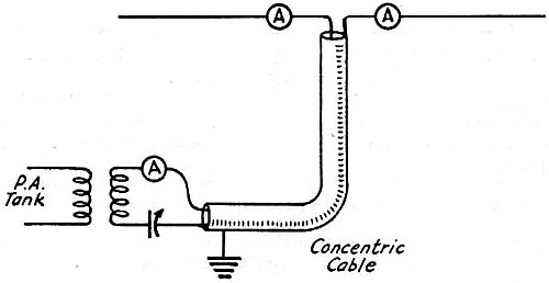
Fig. 2 - A Concentric Cable Line Which Requires No Impedance Matching How do we find out the value of this magical surge impedance for a given line after we have built it? Well, there are two ways. If the line is of a simple geometrical configuration, the easiest and most accurate way is to calculate it from a formula. For two of the commonest types of line the formulas are simple and easy to apply. These cases are parallel solid wires and concentric cables. For ordinary round parallel wires the formula is: Z = 276 log (b/a), (1) where Z is the desired surge impedance in ohms, b is the wire spacing (center to center) in inches, and a is the wire radius (half the diameter) in inches. The logarithm is common or Briggs log to the base 10, found in any trigonometry or engineers' handbook, or the "L" scale on any slide rule. In using this formula two precautions must be taken. First, do not mix units in the values of a and b. You can use inches, centimeters, or anything at all, but a and b positively must be in the same units. Do not use inches for one and mils for the other, or mix centimeters and millimeters. Second, log tables and slide rule scales give logarithms only to the right of the decimal point; you have to supply the part to the left. Here is how it is done. If the value of b/a is less than 10 (it cannot be less than 2, or the wires would touch), there is no figure to left of decimal point; use the value right out of table or slide-rule scale, with decimal point in front. If the value is 10 or more, up to 100, the figure is 1 to left of decimal, and the table value to the right. If b/a is 100 or over, up to 1000, the figure is 2. From 1000 and up as far as 10,000 it is 3, with one added in this fashion for each additional decimal place. Any line with a value of b/a of 10,000 or more would have poor efficiency, however, since it would either be made of very small wire or else spaced so widely that radiation would become appreciable in any but a short length. Practically, it is best to use wire not smaller than No. 14 and spacings not more than 10 inches. In building a line, use only bare wire. Insulation is always bad, especially in wet weather. If you are bothered with corrosion from smoke, use enameled wire. Use only enough spacers to keep the line in shape. In attaching spacers avoid metal pieces, and do not wrap the conductors around the ends of the spacers. I think high-grade glass or porcelain spacers are best, but if you use porcelain be sure it is the best grade and won't soak up water. The concentric cable type of line is more difficult to build, but has certain advantages to be discussed later, so here is its formula: Z = 138 log (b/a). (2) Again, Z is the surge impedance, b is the inside diameter of the outer conductor, and a is the outside diameter (not radius) of the inner conductor. Same precautions as formula (1). Notice that a is radius in (1) and diameter in (2). (This is not the reason why the constant in (1) is twice as big as in (2) however.) Practically, in the concentric cable the greatest problem is in the spacers. Now here is a chance for the whole gang to get busy and figure out something. What we want is some kind of bead to slip on the wire or small pipe forming the inner conductor to keep it uniformly spaced in the center of the larger pipe or outer conductor. We want to be able to bend the cable after assembly without throwing the center conductor very far out of line or breaking the beads. We also want to fasten the beads so they won't slip and so we don't have to use too many of them. We do not want to pack the cable with insulation. Air is best. The beads should be made of good low-loss insulation. Who has some bright ideas? Multiple Quarter- and Half-Wave Lines Uniform lines have some interesting properties if cut to lengths that are exact multiples of a quarter wavelength. If the line length is just
where λ is the wave length and n an integer, 1, 2, 3, 4, 5, etc., then the line acts like a transformer. If it is terminated in its surge impedance, it will still give the same value at the sending end, since this is true for any length. But if it is terminated in anything else, say Zr its sending-end impedance, Zt, will be related to the receiving-end impedance, Zr, and the surge impedance, Zs, by the simple relation,
Stated in words this is: The product of the sending-end impedance by the connected-load impedance is equal to the square of the surge impedance. If a very high impedance is connected at the receiver end, the sending end value will be low, and vice versa. This principle is the foundation of the well-known Zeppelin feeder. An end-fed Hertz doublet has a high impedance. The line is cut to an odd quarter wavelength and acts simultaneously as a feeder and matching transformer, feeding the antenna with a high voltage and small current, while taking a high current and low voltage from the transmitter. This scheme is very convenient and is widely used, but it should be appreciated that there are two important disadvantages. First, the line must be cut to an exact length, which may not suit the location. The length is critical, and swinging due to wind is sure to vary the transmitter frequency unless a very stable m.o.p.a. is used. Besides, one is never sure that the current node is really at the junction. The line is also operated in an unbalanced connection. Second, the line is operated under conditions where its efficiency is minimum instead of maximum. A quarter-wave Zeppelin feeder may have fairly good efficiency, but in the longer multiples the losses are bound to pile up rapidly. Another interesting condition is when the line length is just l = (n/2) λ (5) where the symbols have the same meaning as before. Under this condition the line acts just like a pair of jumper wires of negligible length. Whatever impedance you connect at the receiver end will be duplicated at the sending end, regardless of value. This is not quite true if the value is extremely large or extremely small, but is accurate for most ordinary values. If the line were free of all losses, the statement would be correct for any value; it is an ideal condition which is closely approached. The same thing is true of the formula for the Zeppelin feeder of odd quarter length. At this juncture I think it is about time for the Old Man to touch off a string of profanity and tell me I sound like Final Authority - all theory and formulas, ifs, ands, buts and no results. There is many a slip between pencil and paper, and copper and pyrex. What good is it to know that the surge impedance is 400 or 600 ohms, and must be matched at the load end? We do not care what the value is; what we want is to push the key and see the antenna meter hop. Then we would like to know if the reading we get is the best possible. The problem is just this: After we get the transmitter working O.K. and the antenna and feed lineinstalled, how do we adjust the whole works so we actually get the desired results? Fitting Theory to Practice
Fig.3 - Special case of line of length equal to one or more half waves, in which the impedance looking into the line becomes the same as the load impedance for all values of the latter To begin with, a few remarks about radiation from feed lines might not be out of place. The objective is obviously to make the antenna do all the radiating, and prevent radiation from the line, for two reasons. First of all, the main object of using a feed line is to make it possible to locate the antenna a reasonable distance from all objects that might distort the field and soak up some of the valuable watts that have been generated at considerable cost of labor and money. If the line has an appreciable field of its own its main purpose is defeated at the very start, because its field will react with that of the antenna to produce a resultant which is not what we want, and the line usually passes quite near objects we want to keep out of the intense field, such as tin roofs, rain pipes and gutters, lighting conduit, gas pipes, to say nothing of telephone wires and such things. Secondly, we want the power all at the antenna. Even if the line gives useful radiation instead of loss, we do not want it, because that is not what we set out to accomplish. To prevent line radiation, the circuit must be balanced. By that I mean that the currents in the two wires must be equal and opposite in direction. If they are, the fields of the two wires will cancel. The cancellation is never perfect even though the balance is correct, because the line still acts like a long thin loop antenna of one turn. This effect can be kept small by avoiding wide spacing. Transposition helps but is not a cure, and I believe is more nuisance than it is worth. Here is where the concentriccable line shines; its field is entirely internal. The business end of a transmitter is almost always a tuned circuit (tank). The power amplifier must be given the right amount of loading to make it perform efficiently. The best way to adjust the loading is to use inductive coupling to the plate tank; then an adjustment of loading can be made over a considerable range nearly independently of tuning. The line can be coupled to the plate tank with a simple coil; this is common practice in broadcast transmitters but has the. disadvantage that the reactance of the coupling coil affects the plate tank tuning when the coupling is changed. The best scheme is to use a light (low C) tank circuit on the line. Then the condenser tunes out the reactance of the coupling coil, and it will be found that the coupling adjustment has very little effect on the tuning of the p.a. plate tank. Tuning with the Aid of Dummy Antennas Now the surge impedance of a line has the character of a pure resistance. Hence adjustments are best made with the aid of a dummy resistor. The very best kind is made like a piece of cloth, woven out of resistance wire for the woof and asbestos cord for the warp. These resistors are relatively inexpensive and convenient because they can be adjusted with clips on the edges (selvage). They are relatively non-inductive and have low distributed capacity, which is very necessary for best results. They are not self-indicating, however, and must be used with a meter. Lamp banks are convenient because maximum current can be detected at a glance without a meter, but care must be taken to use them only near their rated power because lamps change their resistance over wide limits with variable input. A common 20-watt 110-volt lamp has a resistance of about 600 ohms at normal brilliance. A pair of 210's in the p.a., a very common combination, should work a 20-watt lamp in good shape. If they do not there is trouble somewhere in the transmitter. Referring to Fig. 1, first connect the dummy resistor to the line-coupling tank as shown at (a). Adjust the coupling for normal load on the p.a. Tuning the plate tank should give a sharp minimum plate current when properly adjusted. Tuning the load tank should give a broad maximum of both plate current and power in the dummy. If the maximum comes at the zero end of the condenser, the coil is too large. If it comes with condenser all in, the coil is too small. Change the coil accordingly, to bring the maximum well on the condenser scale. Note all adjustments carefully. Then remove the dummy and attach the line. Take the dummy outside and attach to the receiver end of the line, Fig. 1b. If the dummy resistance is the same as the line surge impedance, all readings and adjustments will duplicate, so that as far as readings and adjustments are concerned it would be impossible to tell whether the load is connected through a line or right to the tank. If you notice a difference, try a slightly different value of dummy resistance and repeat. It has been my experience with broadcast transmitters that if the dummy is made equal to the calculated line surge impedance, it always works first trial without any fuss or trouble. Incidentally, the value is not at all critical; quite a little variation in either direction will produce only a small effect on tuning and p.a. loading. After this adjustment is finished, note all adjustments and p.a. plate current. Incidentally, this is an excellent opportunity to check up on p.a. .efficiency, since the actual load is known. The next trick is to adjust the antenna connection so that it duplicates the dummy. Matching the Line and Antenna
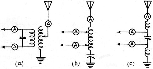
Fig. 4 - Three Methods of coupling transmission lines to grounded antennas The method chosen to match the antenna to the feed line will depend largely on convenience. There are a number of different ways, and if the general principles are kept in mind any of them can be made to work. For frequencies above 14 mc. the direct"Y" connection is the simplest and best for ordinary ladder-type lines arid half-wave Hertz antennas. This scheme was described in detail in QST for December, 1930. To adjust the match, attach the line to the antenna with clips and vary the spread of the clips from the center. The correct adjustment is when the p.a. loading and tuning adjustments agree with those for the dummy resistor. If no satisfactory adjustment can be found, it is probably because the transmitter frequency is not in tune with the antenna. Check up antenna length and master oscillator frequency. For frequencies lower than 14 mc. the Y connection does not work out so well. It is clumsy and becomes difficult to adjust when the spread is large. There are two ways out of the difficulty: Use a matching network; or make the antenna and line match without a network by changing the impedance of one or the other to fit. A half-wave Hertz antenna has a series resistance (at the center) of about 65 ohms at resonance. This is practically independent of frequency; that is, a larger or smaller antenna, driven at resonance by a lower or higher frequency respectively, will have the same resistance. It is not practical to alter this value without adding networks of some kind. So to get a match without a network, it would be necessary to terminate the line with 65 ohms. A little juggling with formula (1) will convince anyone that to build an open wire line with 65 ohms surge impedance is practically impossible. If the spacing is reduced until the wires touch you can only get down to 83 ohms, even if there was no short circuit. But look at the formula for the concentric cable line. Try a value of b/a of 3 or a little less, and you find that if b/a is 2.96, Z is 65. The answer is simple. Use a concentric cable line and connect it directly to the broken center of a half-wave Hertz and forget about matching impedances. Use a series tank to feed it. The outer conductor may be grounded, and the whole assembly makes an efficient lightning rod. See Fig. 2. Another way to do the trick is to use the principle of formula (5). Then any type of line will do, but must be an integral multiple of a half-wave in length. Use the same circuit as for the concentric cable, but divide the condenser just as you would for a standard Zepp feeder. See Fig. 3. This arrangement works exactly like a Zepp system except that the antenna is current fed in the center, and the line length fits formula (5) instead of (3). This arrangement is open to the same objections as the standard Zepp, however. There is high standing wave current in the line, which works at lower efficiency than it would if terminated in Zs. A point of very high voltage will develop in the center of line, so watch out for leaky insulators near it. Ideal potential distributions along the antenna and tuning apparatus also are shown. Grounded Antennas
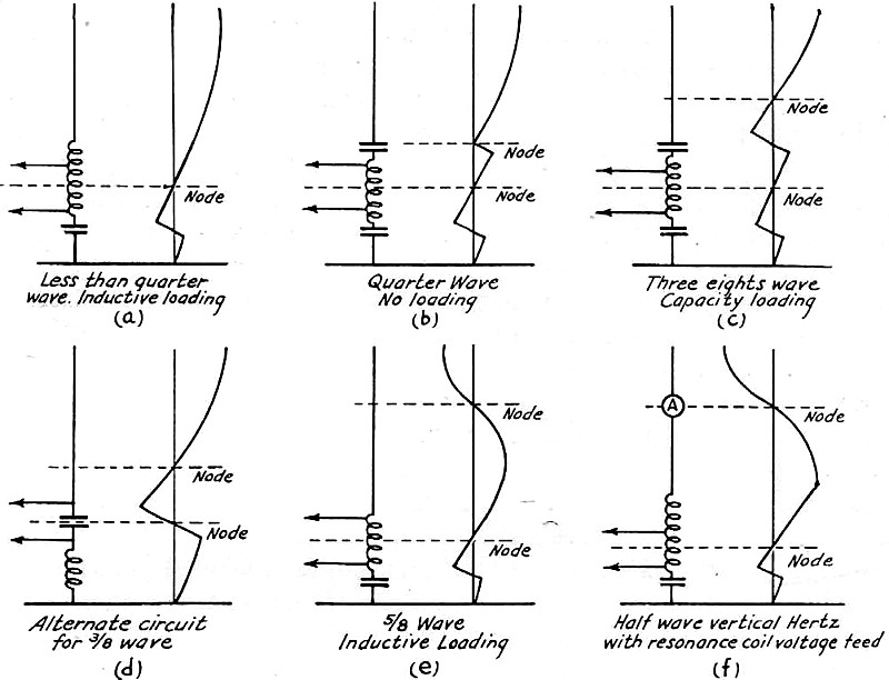
Fig. 5 - The circuit of Fig. 4-b applied to antennas of different lengths The good old Marconi grounded antenna seems to be coming back into favor after several years of neglect. In this case the antenna system is inherently non-symmetrical, and care must be taken to balance the feed line so that the potential node is in the center of the line inductance. Fig. 4 shows some types of feeder connections for grounded antennas. At (a) is shown the most popular circuit for broadcast transmitters. It is not recommended because it is too difficult to tune properly. Every adjustment affects every other, and unless you have had considerable experience with this circuit I would not advise it. At (b) is the most satisfactory circuit for general use. It has no appreciable losses if built decently. High C tanks, as in (a), are effective harmonic suppressors, but exact their toll in losses. An alternative circuit equivalent to (b) is shown at (c). It is equally effective but a little more tricky to adjust, because the potential node, being in the condenser, is not accessible for test. In Fig. 5 is shown the circuit of (4b) for different antenna sizes, along with ideal potential distributions. The coils and condensers serve the double purpose of matching and loading. The method of adjusting is very simple. Proceed to adjust the line .with the dummy as in Fig. 1, then attach line to network and tune to resonance (maximum antenna current). Vary the spread of the line clips until the line currents and p.a. loading are the same as with the dummy. If the number of coil turns is small, giving adjustment in too big steps, replace with a coil of smaller diameter and more turns. Then fish for the nodal point by the touch test method. It should be in the center of the part of inductance included between the line clips. If not, move both line clips together up or down, keeping the spread constant. If in either spread or balance adjustment you run off the bottom end of the coil, reduce the ground series condenser and add more turns in series with antenna. This will move the nodal point up on the coil. If you run off the other end, you will have to change to the circuit shown in 5b. After the balance is adjusted recheck the impedance match with the dummy. You will probably hit it right on the second trip through this procedure. It is not necessary to have a whole flock of thermoammeters; one will do for the line adjustments. Make several bakelite binding post blocks to insert in the various places, and put wire jumpers in place of the meter when it is being used somewhere else. In Fig. 5b the condensers are the same size. In 5c the upper condenser is reduced in size. In 5d the inductance for correct operation will be found to be quite small. The arrangement at 5e is a low-angle radiation antenna of the type that has been given much publicity (WABC), though the line matching network is not that ordinarily used. I want to commend particularly to the amateur fraternity the circuit of 5f. This is a half-wave vertical Hertz, voltage-fed at the bottom by means of a resonance coil. The principle of this has been discussed in QST for July, 1932, page 45. The difference here, of course, is the addition of the feed line. The proper place for the antenna ammeter is half-way up. As before, the meter can be hauled up with the antenna for testing and read with a field glass from a convenient second-story window. For regular service replace the meter with a brass strip having a pair of binding posts on it. At the shorter wavelengths it is possible to remove the ground condenser entirely. The best way to tune the resonance coil is to use a small (peanut type) neon lamp held in the hand. It will glow when the top of the coil is approached even without touching. The spread adjustment will have to be made with the antenna attached. Incidentally, an antenna is a two-way device, and coupling the feed line into the first tuned circuit of your receiver may give you a great surprise on the band used for transmitting. * Consulting Engineer, Assistant Professor of Electrical Engineering, Cornell University, Ithaca. N. Y.
Posted August 12, 2020 |
|

 (3)
(3)  (4)
(4)