December 1966 QST
 Table
of Contents Table
of Contents
Wax nostalgic about and learn from the history of early electronics. See articles
from
QST, published December 1915 - present (visit ARRL
for info). All copyrights hereby acknowledged.
|
As with most hobby and how-to magazines,
QST has had a long-running monthly column featuring handy tips from readers and
sometimes from the column editor's (currently Steve Sant Andrea) own experiences.
It has taken various names over the years such as "Gimmicks and Gadgets,"
"Hints & Kinks, "and now "Hints & Hacks." Steve retired from the column
after 2017, and now there is no byline accompanying it. This installment from the December 1966 QST presents a short
introduction to a VHF "Lazy-H" antenna for mounting in the attic (outdoor restrictions
were common even half a century ago). It is of simple construction using lamp cord
in the configuration and element lengths given - still useful in 2021.
V.H.F. Lazy-H Antenna - An Attic Array for Cliff Dwellers
Gimmicks and Gadgets
Getting an indoor antenna to perform satisfactorily is not always easy. Certain
sacrifices will result from any attempt to install an indoor antenna. Yet, by taking
advantage of broadband antennas and effecting the best possible impedance match
to them, worthwhile results can be secured from an "attic special."
The 2-meter Lazy H described in this article is an old standby which should bring
back a few nostalgic memories to 10- and 20-meter operators who have dabbled with
combinations such as this. The entire system, including 40 feet of 300-ohm ribbon
line, cost the author less than two dollars. It took about 45 minutes to cut the
wire to length, tack the system to the attic wall, and adjust the matching transformer
for an s.w.r. of 1:1. At optimum efficiency this antenna theoretically should be
capable of a maximum gain (bidirectional) of about 5.9 decibels. The overall efficiency
will be governed by the placement of the array with respect to house wiring, water
pipes, gutters and downspouts. The antenna should be kept as far away from such
things as possible, to lessen the chance of pattern distortion, detuning effects,
and absorption of the signal.
Of any number of simple indoor antennas tried for operation on 6 and 2 meters,
the Lazy-H has been superior to all others used.
Making The Antenna
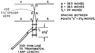
Fig. 1 - Dimensions for the 2-meter Lazy-H antenna. Make certain
that the center sections, B, are transposed as shown.
A 10-foot length of a.c. zip cord was used for the W1CER Lazy-H. The cord was
split at one end and the two conductors were pulled apart, making two 10-foot lengths
of insulated wire. Each wire was pruned to a length of 115.5 inches and pinned to
the attic wall in the configuration shown in Fig. 1, so that their center
sections B-B, crossed. A piece of cardboard, 3 1/2 inches square, was used as a
spacer at the point where the two are transposed, permitting uniform spacing to
be maintained between the phasing line. The insulation was stripped from the wires
at the points marked X, permitting the matching transformer to be soldered into
place. The matching transformer was fashioned from a 20-inch length of 450-ohm open-wire
line.
Tuneup
A Transmatch1 is used at the author's station for coupling the v.h.f.
equipment to the 300-ohm transmission lines which feed the antennas. Initial tests
were made by terminating the transmission line with a 300-ohm noninductive resistor
and applying a few watts of transmitter output power to the line through an s.w.r.
bridge. The Transmatch was adjusted for a 1:1 s.w.r. reading and the dial settings
were noted on paper. Next, the terminating resistor was removed and that end of
the feed line was tapped along T1, experimentally, until a 1:1 match
was obtained at the same setting of the Transmatch controls that gave a 1:1 match
with the 300-ohm termination. The dimensions given in Fig. 1 should be well
within the "ball park" and should provide a close match at 145 Mc. The matching
transformer should be adjusted for your favorite portion of the band. Frequency
excursions to other parts of the band will be possible, but the s.w.r. will rise
somewhat as you depart from the part of the band to which T1 has been
tuned. The Transmatch will permit matching the transmitter to the line and will
disguise the slight mismatch at "off" frequencies, enabling the transmitter to load
up normally. If coax line is preferred, a balun transformer1 can be attached
to T1 in place of the 300-ohm transmission line after the system has
been tuned as just described. This will permit the use of 75-ohm coaxial line, if
desired.
Performance
Since the Lazy-H is a bidirectional array, it should be oriented for maximum
radiation in your favorite direction. In the author's case, north-south directivity
was desired so the array was tacked to the south wall of the attic. Although maximum
radiation is at right angles to the plane of the antenna, some side response exists,
making it possible to work in all directions but with reduced efficiency off the
ends of the antenna.
During an hour of casual listening with an SR-42 transceiver, several W2 stations
in New York and New Jersey were copied Q5 while using the Lazy-H. Stations as far
north as Massachusetts were also received well above the noise level of the receiver.
Many of the stations heard were more than 100 miles away, offering proof that the
antenna was performing satisfactorily.
An antenna of this type should deliver comparable performance on 6 meters, provided
careful attention is given to the dimensions and to the matching. Complete data
covering antennas of this variety is given in the ARRL Antenna Book, Chapter 4.
An outdoor version of the Lazy-H could be fashioned by mounting the elements on
1 X 1-inch lumber support arms. It would then be possible to rotate the array, and
greater efficiency should be possible since the antenna would then be out in the
clear. - W1CER
1 - The Radio Amateur's V.H.F. Manual, pp. 188-189.
Posted September 29, 2021
(updated from original post on 3/16/2013)
|