|
March 1948 Radio-Craft
 [Table
of Contents] [Table
of Contents]
Wax nostalgic about and learn from the history of early electronics.
See articles from Radio-Craft,
published 1929 - 1953. All copyrights are hereby acknowledged.
|
Have you heard of an Alford Loop
antenna? I hadn't until reading this article. It is a four-sided structure consisting
of identical folded ½-wave dipoles on each side, with a common feed. Opposing
sides have their elements 180 degrees out of phase with respect to each other. The
intention is to provide nearly omnidirectional FM radio reception across the entire
88-108 MHz band. A little research on the Alford Loop reveals that
Mr. Andrew Alford developed this configuration to enable
simultaneous, co-located transmissions of FM radio stations. In that case the four
antennas are individually fed by transmitters on different frequencies. Alford is
credited with inventing antenna systems for the
VFH Omnidirectional Range (VOR) and
Instrument Landing System (ILS) navigational aids.
All-Way FM Antenna
By Julian T. Dixon
This antenna has been found to give optimum reception of each of several FM broadcast
stations located in different directions from the receiver. Its response is substantially
independent of direction. Its gain is the same as that of a properly oriented dipole.
It is an Alford loop comprising 4 folded-dipole elements arranged in a square, half-wave
length on a side. Transmitting antennas of this basic type have been described previously
and are in use at many FM broadcast stations.
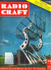
 The antenna components are made of readily available
and inexpensive sections of twin-lead transmission line. The 4 folded-dipole elements
A are made of 300-ohm line and have a terminal impedance of about 300 ohms. The
terminals of the dipoles are connected to a junction in the center of the antenna
through equal lengths B of 300-ohm line. The B sections may be made long enough
to provide sufficient slack to prevent pulling the dipoles out of shape. The antenna components are made of readily available
and inexpensive sections of twin-lead transmission line. The 4 folded-dipole elements
A are made of 300-ohm line and have a terminal impedance of about 300 ohms. The
terminals of the dipoles are connected to a junction in the center of the antenna
through equal lengths B of 300-ohm line. The B sections may be made long enough
to provide sufficient slack to prevent pulling the dipoles out of shape.
Since the B sections are effectively in parallel at their junction, the impedance
there is one-fourth of 300 ohms, or 75 ohms. The standard receiver input impedance
is 300 ohms; consequently a quarter-wave length section C of 150-ohm line is used
to step up the 75-ohm impedance at the junction to the 300-ohm impedance of the
line D to the receiver. The D section may be of any length sufficient to reach the
receiver.
It was found that an antenna constructed according to the dimensions shown worked
well over the entire FM broadcast band, 88 to 108 megacycles, although it was cut
specifically for 100 megacycles. S-meter readings indicated an improvement of as
much as 17 decibels over the dipole previously used, for signals from stations which
were not in the broadside direction of the dipole. For signals arriving from the
dipole broadside direction, the loop gave an equal input to the receiver.
Less fading due to reflection of the signal from airplanes overhead was noted
with this loop, as compared with the dipole. This improvement is attributed partly
to the fact that the loop has some directivity in the vertical plane, giving maximum
response at zero degrees elevation and decreasing to zero response at 90 degrees.
Signals reflected from airplanes above the horizon are thus rejected to some extent.
Signals arriving from the dipole minimum direction had been especially subject to
flutter fading due to the reflected signal being received from airplanes which were
broadside to the dipole. This condition was remedied by the omnidirectional response
of the loop in addition to its vertical plane directivity.
The loop must be mounted in the horizontal plane and the C and D sections should
drop away vertically from the junction of the B sections for a distance, preferably,
of 5 feet or more. The dipole elements may be suspended conveniently from the ends
of 2 light diagonal wooden supports. For an attic installation, four nails can be
driven into the rafters as supports.
Care should be taken to connect the components exactly as shown. The 180-degree
twist in 2 of the B sections as shown provides the required 180-degree phase relationship
of opposite dipoles while maintaining an in-phase condition around the perimeter
of the loop.
The dimensions of the antenna components in wave lengths are given below for
the convenience of those who may wish to construct similar antennas for use on other
frequency bands.
Section Length
A
0.45 wave length
B
0.25 wave length (or more)
C
0.193 wave length (see note)
D
any length
Note: Length of C section is 0.25 wave length multiplied by 0.77, the velocity
constant of the 150-ohm line.
A Teleran experimental installation is being made near Washington, D. C., for
operational tests of the new navigational aid. Teleran is a name coined from the
words Television-Radar-Air-Navigation. The unique system of air navigation and traffic
control combines ground search-radar and television to furnish the pilot a constant
"aerial roadmap" on a screen on his instrument panel. This composite pictorial presentation
of route, terrain, traffic, and weather data clearly identifies all mountains and
other obstacles to aviation, and is expected eventually to make all-weather flying
a practical reality.
Posted May 21, 2022
(updated from original post on 12/29/2014)
|


