A.C. Generator for Automobiles
|
|
AC alternators replaced DC generators back in the 1940s as demand for conditioned electrical power in vehicles rose beyond that needed for ignition and lighting. Radios are the most notable additions, and because amplitude modulation (AM) broadcasts were the dominant method of the day for commercial stations, noiseless electrical supplies were required. Spark-induced noise from ignition systems was bad enough since its frequency varied with engine RPM, but the DC generator's commutator sparking noise - much of it right smack in the audio frequency range - was just too much for the public to endure if widespread acceptance of radio was to be realized. Remember that in the era, a radio was not standard equipment in cars and trucks so customers needed to be convinced the extra expense would be worth their hard-earned dollars. Use of a 3-phase alternator reduces the component performance requirements for conversion to DC. A. C. Generator for Automobiles
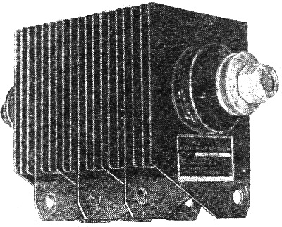
The alternating current motor car generator.
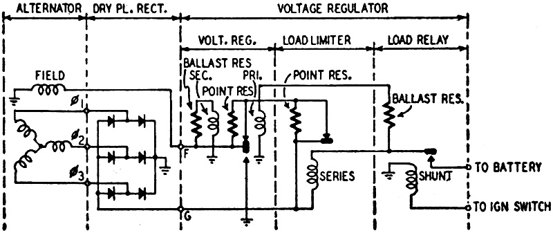
Rectifier shown in the schematic at bottom. The old problem of how to maintain adequate charge in the automotive storage battery used to operate mobile radio equipment and public address systems appears to have been solved through the use of an a.c. alternator to replace conventional d.c. generating equipment. Application of the alternator in combination with a voltage regulator and dry disc rectifier results in obtaining much higher electrical output at all engine speeds. This new a.c. generating system was developed by The Leece-Neville Company, of Cleveland, Ohio. The use of d.c. in automotive equipment came about as the simplest solution to the problem of a portable power supply: the wet cell type battery. To eliminate the constant design compromise required in a d.c. generator, and at the same time solve the problem of a flat output curve for wide variations of engine speed, the designers turned to an alternator. Output of the alternator is taken from a 3-phase stator, thus eliminating sparking and brush wear, the 2 major problems of commutation in a d.c. generator. The stator is Y-connected, giving a voltage conversion factor of 1.732 times that of any single leg. This a.c. output is applied to the 3-phase full-wave rectifier unit, composed of pre-aged magnesium-copper-sulphide plates which in effect replace the commutator of a d.c. generator, since d.c. output is obtained. The control unit of the system is composed of 3 sections: a voltage regulator; load limiter; and load relay. The voltage regulator and load limiter are connected to control the field current of the rotor as a function of load voltage or current regardless of engine speeds above 575 r.p.m., and load demands within the capacity of the system, where the alternator ratio is 2:1. The Leece-Neville a,c. generating system provides a flat performance curve of 60 amperes from 11 1/2 m.p.h. up to a maximum speed of 120 m.p.h. with a 35-ampere capacity at engine idling speeds. This is in comparison with the heavy-duty generator system most commonly in use with the following performance: maximum output of 40 amperes from 19 1/2 m.p.h. to 53 m.p.h., and an 18-ampere output while idling at 450 revolutions per minute.
AC Generator & Rectifier Schematic
Posted May 17 2022 |
|