|
October 1945 Radio-Craft
 [Table of Contents] [Table of Contents]
Wax nostalgic about and learn from the history of early electronics.
See articles from Radio-Craft,
published 1929 - 1953. All copyrights are hereby acknowledged.
|
Don Hoefler, widely
credited for being the first author to use the term "Silicon Valley" in print*
to refer to the rapidly building semiconductor region of the San Francisco Bay
area, published a series of articles in the 1944-1945 timeframe in
Radio-Craft magazine about radio and television broadcast equipment. This
particular installment is part XII, covering broadcast antenna towers. At the
time, commercial installations were few and far between as priority was given to
scarce resources for military applications. He discusses the tradeoffs involved
in various vertical antenna designs, including the tower structures:
top-loading, center-loading, etc. When I first looked at the traditional tapered
tower design I thought about how labor-intensive such calculations might be and
sure enough, he mentions that constant-cross-section towers were gaining favor
due to the relative ease of computations for predicting radiation patterns and
impedance matching. Still, it required a lot of slide rule work to plot enough
points for useful 3-dimensional patterns, and even then results were nowhere
near as good at predicting outcomes as readily available software like
EZNEC. BTW, check out the announcement that
beginning January 1, 2022, EZNEC will be a
FREE download since creator
Roy Lewallen, W7EL, is retiring!
* January 11, 1971
Electronic News newspaper, page 1. Here is the first Archive.org
capture (July 1998) of
Electronic News.
Broadcast Equipment
Part XII - Broadcast Antenna Towers
By Don C. Hoefler
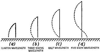
Fig. 1 - Current distribution on various heights of straight-wire
vertical broadcast antennas.
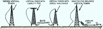
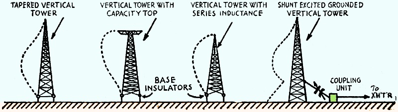
Fig. 2 - Current distribution on several types of broadcast towers
under optimum conditions.
Probably all of the antennas used in early broadcast practice consisted of some
form of multi-wire arrangement, such as the T, inverted L; though sometimes a single
vertical wire, all of these were operated above their natural fundamental frequency.
These were suspended between two tall structures (usually self-supporting steel
towers), spaced some. distance apart. Later, as the advantages of vertical polarization
were discovered, experiments were made with various types and sizes of vertical
steel towers, which themselves acted as the radiators.
Most of the developments in tower design have occurred since 1927. For several
years, the guyed cantilever ("cigar-shaped") structure was considered to be the
very last word in broadcast antenna design, and a number of them are in use today.
Then, development work reverted to the broad-based self-supporting type, and most
recent practice favors the uniform-cross-section structure, which may be either
guyed or self "supporting.
Efficiency of Propagation
The directivity in the vertical plane of a vertical antenna is determined in
part by its natural wave length. Current distribution in straight single-wire vertical
radiators of various heights is shown in Fig. 1. In broadcast work it is desirable
to have as much of the radiated power as possible be emitted as ground wave, with
an absolute minimum of high-angle radiation. This will increase the primary service
area, and reduce fading and interference at remote points. Practical experience
has proved that best results are obtained when the radiator is either approximately
one-quarter wave length or slightly over one-half wave length.
Ballantine demonstrated that the optimum condition of power efficiency, considering
maximum ground-wave radiation and maximum sky-wave suppression, occurs when the
effective antenna height is around 0.50 to 0.56 wave length. This corresponds to
an actual physical height of 0.62 wave length. This indicates that the advantage
of initial cost in a quarter-wave antenna is not as great as might first appear,
for while the effective height of the half-wave structure is roughly 85-1/2% of
the physical height, the effective height of the quarter-wave vertical radiator
is only 64% of the actual height.
Up to the condition of optimum efficiency, the effective signal strength available
at a receiving antenna is determined by the meter-amperes at the transmitting antenna.
This figure is the product of the effective antenna height in meters and the effective
antenna current in amperes. This does not indicate any factor of the antenna power,
but is an arbitrary figure which demonstrates that the effective signal increases
with the antenna height, This fact holds true up to the optimum condition, but beyond
that the second lobe of the standing wave would be in phase opposition with that
of the first half-wave section, as shown in Fig. 1 (D).
Attempts to approach the optimum radiation condition while avoiding the expense
of a fully optimum-height tower have led to some rather interesting developments
in tower construction. Fig. 2 shows the current distribution for several common
types of antenna towers operating under optimum conditions. When the tower is insulated
from ground, the exciting voltage is simply applied between the base and ground.
The grounded antenna employs a somewhat different method of excitation, to be discussed
presently.
The Top-Loaded Tower
The capacity-top arrangement permits the height required for optimum operation
to be reduced somewhat, but when used alone this is hardly enough to be practicable.
However, the sectionalized tower with series inductance permits a reduction in total
height of 20% to 30%. There is an additional advantage in that it is possible to
vary the effective height of the tower by adjusting the series inductance without
involving expensive structural changes. The disadvantages are the additional expense
of sectionalizing the tower and the losses of energy occurring in the inductance.
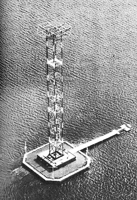
Station WABC, New York, uses a combination of these two types of construction, known
as "top-loading." A site in Long Island Sound known as Columbia Isle (formerly Pea
Island) was selected because of the excellent coverage that a transmitter located
there would provide. However, due to the proximity of New York Municipal airport,
Flushing Airport, and Westchester County Airport, a tower of optimum height would
create a hazard to the large volume of aircraft traffic. Top-loading proved to be
the solution. Since the theoretical optimum of a broadcast tower is predicated upon
a current distribution which places the current maximum at a point 0.375 wave length
from the base of the tower, designers attacked the problem of a smaller tower for
optimum operating conditions by attempting to establish electrical control over
this anti-node by some means other than altering the tower size. It was found that
since the L/C ratio along the length of the tower determined the location of the
loop, this value could be varied by connecting a variable amount of lumped capacity
or inductance near the top of the tower. Hence the term "top-loading." The WABC
system represents the latest advance in broadcast antenna design in the use of a
uniform cross-section tower. This enables the electrical characteristics of such
a radiator to be calculated accurately; whereas any structure involving a taper
introduces variables which can often be determined only by actual experimentation,
a method which may prove very costly.
The Shunt-Excited Tower
The shunt-excited antenna is a vertical tower with its base grounded, and which
is excited at some point above ground. This system makes use of a loop formed by
the ground and the exciting transmission line attached to the tower at a point above
it. The coupling arrangement at the antenna end is simply a variable condenser in
series with the exciting conductor. This wire runs from the coupling unit to the
antenna, is usually inclined at an angle of about 45 degrees and is tapped on to
the tower at a point corresponding to approximately 20% of the height. A connection
at this point bas a resistance of 100 ohms or less, which permits a concentric type
transmission line to be matched to the tower. The loop thus formed is tuned to the
carrier frequency by the series condenser, and carries a large circulating current.
This develops sufficient voltage across the section of the tower included in the
loop to excite the remainder of the tower. Since the tower itself is grounded, much
less trouble with program interruptions due to lightning and other static discharges
is encountered. As a result the cost of lightning-protection devices is saved. Another
saving is in the elimination of the large and expensive base insulators. All tower
radiators have the advantages of simplicity, low cost, and high efficiency.
Problems of Grounding
The ground system surrounding the tower base is a problem of exceedingly great
importance, for upon it largely depends the overall efficiency of the radiation
system. If the earth exhibited a characteristic even approaching perfect conductivity,
any firm connection to it would provide a satisfactory termination. However, all
soils including even salt-water marshland, are poor conductors at radio frequencies.
Therefore, the ground system associated with the tower must make the best possible
contact with the existing terrain. Although it was at first believed that a ground
system extending to the practical limits of the induction field was sufficient,
it has been found that, in order to serve effectively as a reflecting surface for
the downward radiation, the ground system must extend outward considerably beyond
this distance.
The ideal ground system would be a solid sheet of some material having a high
conductivity and covering an extensive area in all directions surrounding the base
of the tower. Although such a system would be prohibitively expensive, much theoretical
and experimental work, due to Brown1, has resulted in certain definite
standards for the design of broadcast tower ground systems which approach the ideal.
120 buried radial conductors, spaced 3 degrees apart, and extending outward from
the base of the tower in straight, lines not less than one-half wave length at the
operating frequency comprise such a "near-ideal" broadcast ground. This length is
quite necessary, for when it is less the ground losses increase considerably even
when the physical height of the antenna is small.
Other Considerations
In most instances it is necessary to provide the tower with a system of aircraft-warning
lights. In order that the radiated energy will not be shunted to ground through
the 60-cycle power line, it is necessary to supply the lights through a low-pass
filter inserted in the line. This consists simply of an R.F. choke in series with
each side of the line, and a condenser across the line at each end of the chokes.
Steel buildings, trolley wires, guy wires, and other conductors in the vicinity
of the tower will alter its radiation pattern, so an antenna site must be chosen
with care. Guy wires must be as few as possible, and they must be broken up by insulators
into lengths that are a small part of a half wave length. Transmission lines must
approach the radiator at right angles for minimum couplings.
In northern climates, where trouble is encountered due to sleet and ice, a de-icing
system must be installed. This consists of a means of passing a heavy 60-cycle heating
current through the tower itself to melt the formations. Since it is desirable that
this function may be carried out while the station is "on the air," a low-pass filtering
system, similar to that used with the warning lights but more elaborate, must be
employed.
1) Brown, G. H., "The Phase and Magnitude of Earth Currents Near Radio Transmitting
Antennas," Proc. I.R.E., February, 1935; "Ground Systems As a Factor in Antenna
Efficiency," Proc. I.R.E., June, 1937.
Posted August 9, 2021
|