Coils, Cores and Magnets
|
|
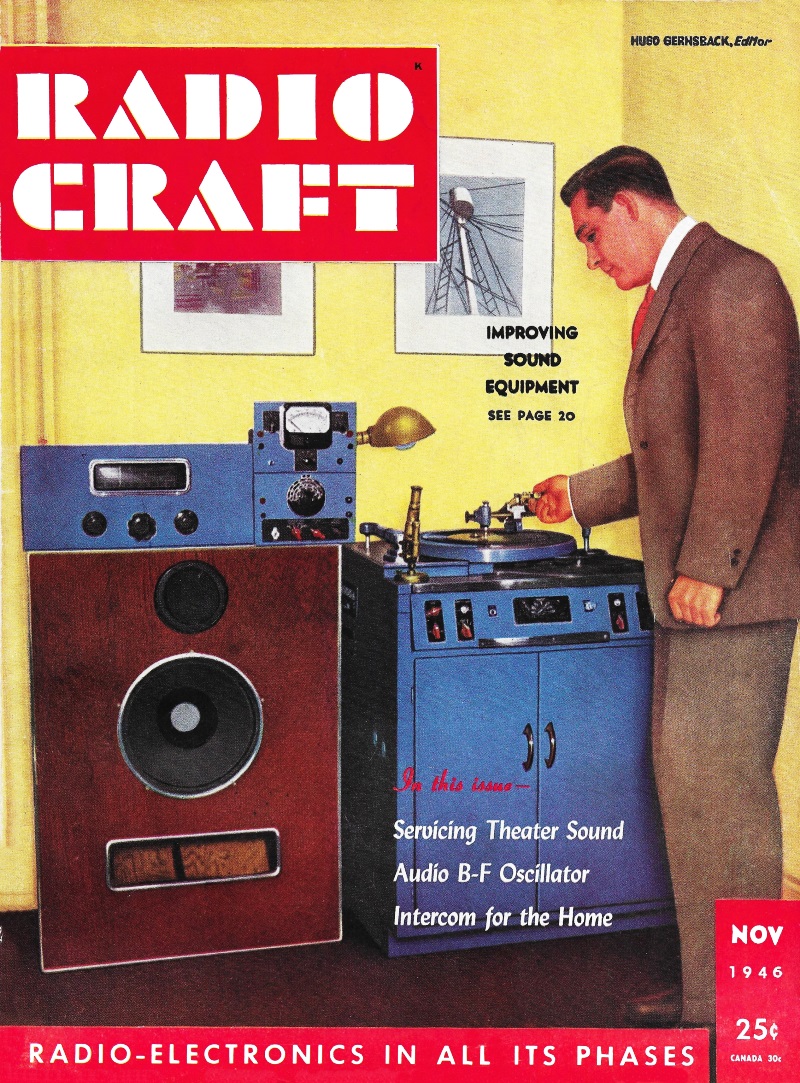
This very extensive article on iron-core inductors appeared in the November 1946 issue of Radio−Craft magazine. The first part, published the month prior in October, was an introductions to terms of inductance and magnetism, while this one deals with actual design curves and formulas. Iron core and air core inductors are the focus, and as you might guess (due to the use of iron cores) the frequency range addressed is audio and relatively low intermediate frequency (IF). In fact, separate treatment is given to coils operating at DC (direct current) and AC (alternating current). Back in the day, not only were most of the components inside a radio, television, record player, or other types of electronics devices serviceable (i.e., replaceable), but the components themselves were considered serviceable. That is, inductors, speaker coils, transformers, and even some capacitors were often repaired or modified to fix non-working circuits or to improve marginally functioning ones. Coils, Cores and Magnets - Part II - Reactor and Transformer Measurement and Design
Iron-Core Inductance Design Nomograph By H. W. Schendel Filter chokes or reactors, audio-frequency chokes, and audio transformers come under the classification of iron-core inductances. The unit of inductance is the henry. A coil has an inductance of one henry if a current changing at the rate of one ampere in one second induces one volt in it. Basically inductances are the same as electromagnets and use cores like the relays described in the first part of this article. The essential difference is that inductance is the main consideration. This in turn depends on the permeability of the steel or alloy. Considerable care is required in rewinding good grade audio devices but it is a comparatively simple matter to rewind filter chokes and obtain approximate original characteristics. If a unit is rewound with original size wire, with about the same number of turns, and close attention given the size of air gap, if any, no trouble should be encountered. When an air gap has been used its size is extremely important. In some cases a change of 0.001 inch in air gap total length will cause a 50 percent change in final inductance. Generally speaking it is better to err slightly oversize rather than undersize. Much valuable information on rewinding, including a copper wire table, appeared in articles in the August, September, October, and December 1942, and the September 1943 issues of Radio-Craft. To rewind an iron-core inductance for other than original conditions or to design one for some specific purpose involves several factors.
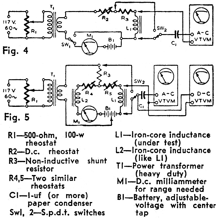
Fig. 4 & Fig. 5 - Inductance measurement configurations.
Inductance Formulas - Symbols and equivalent English and C.G.S. units of common magnetic terms and formulas. Windings of iron-core coils carrying only a.c. have an inductance which varies in relation to the induced flux in a manner similar to the variation of the d.c. permeability obtained from Fig. 1, which appeared last month. Push-pull output transformers in which the d.c. effects cancel and inter stage transformers which have the d.c. blocked from their windings are examples of the simple a.c, class. Most iron-core inductance windings carry both a.c. and d.c. simultaneously - a.c. superimposed on d.c. As either of these may be varied in magnitude it is easy to see there would be an almost endless number of conditions, each resulting in a different inductance. The inductance rating of any device is accurate only when the test conditions are the same as the normal load conditions. Curves may be prepared showing the a.c. flux density (Bmax-ac) versus a.c. permeability (μac) for various values of d.c. in the winding. Such curves prepared from test data on a special test core are called incremental permeability curves. Due to the factors explained in connection with d.c. magnetization curves as well as other factors - eddy-current insulation, stacking factors, core shapes and sizes, and other characteristics of laminations - separate permeability curves are needed for each core design. The curves, when prepared from data obtained directly from a definite working design, using a specified steel or alloy, are called apparent permeability curves (μa). They indicate the actual permeability (not theoretical) which the design appears to have under selected working conditions. An air gap is seldom used when the inductance is used only on a.c. except in such devices as fluorescent lamp and sunlamp ballasts. Lamp ballast design must permit sufficient current to flow through the ballast for normal operation, make available enough starting voltage, yet limit the current to a safe value at all times. Most inductances having d.c. in the windings have an air gap in the magnetic circuit. This is to increase the apparent permeability over that available without an air gap. The length of air gap which results in highest permeability and likewise highest inductance for the particular current conditions in the windings is called the optimum air gap. Optimum air gap may be computed by proper application of the normal d.c. magnetization curve and the incremental permeability curve for a given steel and core. The procedure is rather lengthy and will not be presented here. The average experimenter would probably find it faster to use a test circuit and obtain apparent inductance, apparent permeability, and optimum air gap simultaneously. Circuits suitable for measuring inductance, determining apparent permeability and optimum air gap, are shown in Figs. 4 and 5. The Fig. 4 circuit is suitable for low and zero direct current. D.c. saturation of the transformer core is eliminated with the Fig. 5 circuit but the circuit has the disadvantage of requiring two similar chokes. In either circuit the d.c. is first adjusted to the normal working condition. R4 and R5, Fig. 5, must be so adjusted that no d.c. flows through R3. This can be determined by a d.c. v.t. voltmeter across R3. Sufficient a.c. voltage is applied to give the working values across L1, as measured by an a.c. v.t. voltmeter. Connecting it across R3 will give the voltage drop due to the a.c. flowing through L1. The optimum air gap may now be found by varying the gap length until the a.c. voltage across R3 reaches a minimum with the a.c. voltage and direct current across L1 held to the working values. For Fig. 5 the air gaps must be the same for L1 and L2 and both varied simultaneously. Inductance Formulas The apparent inductance of L1 in henries will be
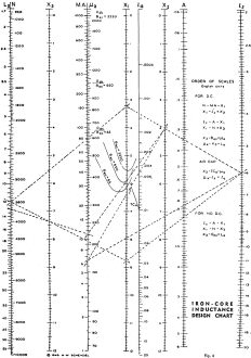
where R3 = d.c. resistance of voltmeter shunt in ohms, EL = a.c. volts across L1, ER = a.c. volts across R3, f =a.c. test frequency, and Ra =apparent resistance of L1. (Ra consists of the d.c. resistance plus resistance effects due to core losses. The latter are very low in good-grade laminated cores.) Usually Ra is small compared to the inductive reactance of the coil and could be omitted, simplifying the formula to La = 0.159 R3 EL) / f ER Because L1 and L2, Fig. 5, are in parallel, La must be multiplied by 2 to obtain the value for L1. Knowing La, the apparent permeability can be found to be μa = (108 1 La) / (3.19 N2 A K1) where 1 length of core in inches, A = area ,of core in square inches, N = number of turns in coil, and K1 = stacking factor (usually about 0.9). The a.c. flux density in lines per square inch will be Bac = (108 Erms) / 4.44 f N A K1 where Erms = a.c. voltage across L1 and other symbols as before. To simplify calculations for average cores an Iron-Core Inductance Design Chart has been constructed in Fig. 6. The symbols at the scale headings may be identified from the previous text. The multiplying scales X1 X2, X3 are used to obtain readings. The Inductance Design Chart is constructed to automatically allow a 0.9 lamination stacking factor. Odc points, and the Bac and TCa turning curves were prepared from data on 29 gauge (0.014-inch) steel laminations having properties similar to those on Curve 1, Fig. 1, which appeared last month. These properties were taken as an average. Some steels will give more inductance, others less. Now points and turning curves may be constructed for steels and cores with other characteristics. The balance of the chart would remain unchanged. The previous Bac formula may be used to assist in selecting one of the Bac turning curves or Odc points on the chart. Values of Bac may be less than 65 for some interstage a.f. transformers and smoothing chokes while for some output transformers and swinging or input chokes it may go well beyond 3500. Turning curve TCa is used to obtain air gap length for all values of Bac. Use of the Chart Assume we have a core like Fig. 3 (last month's issue) to be used for a smoothing choke. The core is 1 inch wide and stacked 1 inch high using 29 gauge (.014-inch) steel laminations, making the area (A) = 1.0 square inch. The entire core has uniform cross-sectional area (each of the two outer legs have one-half the area of the center leg). The core length (average length around each window as indicated in Fig. 3) ls = 6.0 inches. Window is 1/2 x 1/2 inch. Bac = 650 will be satisfactory and there will be 80 ma d.c. in the windings. The problem is to find the maximum inductance, La in henries, and the optimum air gap, la, in inches. The more turns the greater the inductance but wire size, allowable resistance and window area will limit the number. Wire size and coil dissipation watts may be computed as outlined for electromagnets. If the coil resistance is too great larger wire may be used. A fairly reliable method is to select a wire, allowing 750 to 1250 circular mils per ampere. A wire table and a few computations will show that 3500 turns, No. 32 enamel wire, would go in the window and have a resistance of about 250 ohms. This information may now be applied to the Inductance Design Chart, Fig. 6. The column headed "Order of Scales" indicates the function of certain groups of scales and under each function is given the order in which the scales are read at each setting of a straightedge. Mistakes will be prevented by writing down the reading for each scale. Using the group of scales "FOR D.C." set a straightedge from 3500 (no. of turns) on N to "80 (no. of milliamperes) on M.A. and read 3.23 on X1; From 3.23 on X1, to 6 (lgth. of core, inches) on ls and read 4.02 on X2; Next from 6 (core length) on ls to 1 (core area, sq. in.) on A and read 8.78 on X1; From the 8.78 on X1 to 3500 (no. of turns) on N and read 7.38 on X3; From 4.02 previously obtained on X2 over the Bac = 650 curve and read 222 on μa; From 222 on μa to 7.38 previously obtained on X3 and read 13 on La, the apparent inductance in henries. The optimum air gap may be found by using the "AIR GAP" group of scales. From 4.02 found above for X2 over the point of the TCa curve read 170 on μa; From 170 on μa to 6 (core length) on ls and read 0.0153 on la, the total length of the air gap, in inches. (See Fig. 3.) Although not a part of the problem let us suppose there is .no d.c. in the windings. What will be the inductance? For this we use the "NO D.C." group of scales. To proceed set a straightedge from 6 (length of core) on ls to 1 (area of core) on A and read 8.78 on X1; From 8.78 on X1 to 3500 (no. of turns) on N read 7.38 on X3; From 7.38 on X3 to Odc / (Bac = 65) point on μa and read 37 on La, the apparent inductance in henries. If Bac is nearer 650 than 65, the La would be over 60 henries. No air gap would be used. Instead, the laminations would be interleaved as on any transformer. Transformers, Swinging Chokes Audio frequency and output transformers are designed mainly on the basis of inductance of the primary winding, making the design problems similar to chokes except that secondary windings follow regular transformer procedure for impedance and turns ratios needed. Inductance values range from 2 to 50 henries and more, the higher inductance values giving better low frequency response, especially when used with tubes having high plate resistance. Swinging chokes are often desirable when the load varies widely. The main difference between a swinging and smoothing choke is that the former, though designed for high d.c., has a shorter than optimum air gap. This shortened air gap lowers the inductance considerably at high d.c. loads and increases it at low d.c. loads when compared to a choke designed for high d.c. only. The Fig. 6 chart is useful only for rough design of a swinging choke. Select the wire for the maximum d.c. ma and assume some value for turns to fit on the core. From the chart determine La at maximum d.c. and multiply the value found by 0.58 for the actual minimum swinging choke inductance. If this figure proves to be unsuitable try again using new values for turns or core. After suitable values have been found for the maximum d.c. use all of them except that in place of the maximum d.c. ma substitute a value only 10 per-cent of the maximum d.c. ma and find the length of optimum air gap from the chart. Multiply the length as found by 2.6 to find the total air gap length to use for the swinging choke. Inductance ratio between maximum and 10 percent of maximum d.c. will be about 4 to 1. A shorter air gap would increase the ratio but would decrease the inductance at maximum d.c. A handy reference chart of conversion factors and formulas (see page 27) shows some unusual variations. Unidentified symbols are explained in the text. Acknowledgement is given Allegheny Ludlum Steel Corporation, United States Steel Corporation, and American Rolling Mill Company for information on electrical steels.
Posted February 7, 2022 |
|